
Using convergent half width half Maximum(c-HWHM) tilting method to determine the virtual source posi
Using convergent half width half Maximum(c-HWHM) tilting method to determine the virtual source position of scanning-pass scattering beam in carbon ion therapy
Yi-He Zhanga,#, Yan-Cheng Yea,#, Yan-Shan Zhanga,Jia-Ming Wua,b,c,*,1
a Heavy Ion Center of Wuwei Cancer Hospital, Gansu Wuwei Academy of Medical Sciences, Gansu Wuwei Tumor Hospital, Wuwei City, Gansu province, China
b Department of Medical Physics, Chengde Medical University, Chengde City, Hebei Province, China
c Department of Radiation Oncology, Yee Zen General Hospital, Tao Yuan City, Taiwan
Keywords:Carbon ion beams,Virtual source position,Scanning-passive scatter beam
ABSTRACT:
Introduction: We developed a half-width half-maximum tilting angle convergent method to replace the conventional measurement of the virtual source position for scanning-pass scattering beam in carbon ion therapy.
Materials and methods: A homemade large-format CMOS sensor and Gaf Chromic EBT3 films were used for the virtual source position measurement. The Gaf films were embedded in a self-designed rectangular plastic frame to tighten the films and set up on a treatment couch for irradiation in the air with the film perpendicular to the carbon ion beam at the nominal source-axis-distance (SAD) as well as upstream and downstream from the SAD. The radiation rectangular field size in horizontal and vertical directions on film or detector delivered by 5 carbon ion energies were analyzed separately in this study. The virtual source position was determined with film or detector at a distance upstream or downstream from the various source-film-distance by the half width half maximum tilting angle convergent method to compare the results conducted with the same measurement condition by the back projecting the FWHM to zero methods.
Results: The determination of virtual source position by using half width half maximum tilting angle convergent method agrees with the method by back projecting the FWHM to zero, and for higher carbon ion energy has an obvious longer virtual source position since the more carbon ion beam energy, hence, the less side scatter results in the less divergent at the downstream, then the virtual source positions is distal for high energies than low energies when back projects the field sizes to zero.
Conclusion: We have developed a technique capable of dealing with the virtual source position with a geometric convergent method to avoid any mistakes in the passive scatter carbon ion beam. The method for investigating the virtual source position in the carbon ion beam in this study can also be used for electrons and proton beams.
Using Convergent Half Width Half Maximum(c-HWHM) Tilting Method to Determine the Virtual Source Position of Scanning-Pass Scattering Beam in Carbon Ion Therapy
1.Introduction
The carbon ion beam, unlike an electron beam from a linear accelerator, does not originate from a physical point source in the nozzle acceleration system (Shroder-Babo, 1983; Jamshidi et al., 1986; Khan et al., 1978; Gottschalk et al., 1993). A narrow energy-dependent spot size of the carbon ion beam, after passing through the horizontal and vertical scanning magnets in the vacuum window of the accelerator, primary collimator, beam monitor, raster scatterer, ridge filter, and ridge shifter, and range shifter, is scanned spreading into a broader two-dimensional field that appears to diverge from a point. This point is known as the virtual source position (Bortfeld and Schlegel, 1996), which may be defined as an intersection point of the back projection along with the most probable directions of carbon ions motion at a fixed position, for example, on the plane at a nominal source-axis-distance. There are many investigations describing the method of determining the virtual source position by inverse square law correction for output at extended SSDs (Source to Skin Distance) under all clinical conditions or by field size magnification on film with distance (Kimstrand et al., 2007; Kooy et al., 2003, 2005; Petti, 1992). Despite a lot of methods that have been proposed for the determination of virtual source position for medical linear accelerator electron beams and proton beams, none for heavy charged particles-like carbon ions have been investigated (Petti, 1996; Russell et al., 2000). Usually, the virtual source point of the electron beam in radiation therapy needs to be measured by the back projection of the 50% width of the beam profiles acquired at different distances upstream or downstream. (Meyer et al., 1984). The largest field size without the collimation of multi-leaves collimator (MLC) in our facility was used for measurements in this study. The measurement of virtual source position for carbon ion beams differs from electron beams since the inverse square law used in electron beam correction cannot be applied to the measurement of the carbon beam’s percent depth dose curve on the plateau at different distances.
The Institute of Modern Physics (IMP) was founded in 1957 in Lanzhou, China. [8]. The facility of WuWei Heavy Ion Center, Wuwei Cancer Hospital, GanSu, China (WHICH) consists mainly of a synchrotron ring for accelerating sufficient particle energy and enough flux for four treatment rooms. Room 2, equipped with a horizontal, and a vertical nozzle aimed at one isocenter with passive scatter ion beams, was conducted in this study. The importance of the virtual source position not only fits the need of correcting the opening of the multi-leaf collimator in field sizes but also supports the fabrication of compensators for carbon ion therapy for the patient-specific dosimetric calculation in the treatment planning system.
It is realized the virtual source positions of the electron beam are highly energy-dependent, if the issue is also highly energy and field size-dependent for the carbon ion beam then the virtual source position needs to be measured carefully for each carbon ion energy, therefore, the virtual source position of five carbon energies, 120, 190, 260, 330 MeV/u, and 400 MeV/u at WHICH were investigated.
The half-width half maximum tilting angle convergent method was used to double-check the virtual source position measured by the conventional back projecting zero methods to minimize mistakes caused by manual measurement by exposing a certain field on CMOS sensor and films at some distance upstream and downstream from nominal source-axis distances.
2.Materials and Methods
A horizontal carbon ion beam equipped in room 2 was adopted for the virtual source position measurement in this study. The construction and physical geometry dimension outlet of our carbon ion facility is shown in Fig. 1. The horizontal carbon ion beams pass a horizontal scanning magnet first leads to particles moving at the x direction (horizontally) and then penetrating into a vertical scanning magnet second leads to particles moving at the y direction (vertically) to create the scanned field size in the x-y directions for clinical use. The ridge filter, ridge shifter, and range shifter, as well as compensator, were removed with only the primary collimator opened during the measurement in this study.
Five carbon ion energies from 120 MeV/u in an increasing interval of 70 MeV/u to 400 MeV/u with serious field sizes were carried out for the measurements of the virtual source position atour institute in this study. The width between the dose of 50% of the central axis derived from the dose profiles was measured and defined as the full-width half maximum (FWHM). The width of FWHM of different field sizes at its relative upstream or downstream setup was plotted with its reciprocal distances from the nominal SAD for investigating the virtual source position of carbon ion beams.
The linear relationship of the beam’s FWHM in the air appears to diverge geometrically from a point source, the virtual source position, where the beam’s field size is 0 when projecting upstream or downstream field sizes back along the central axis. On the contrary, the tilting angle θ in the c-HWHM method at different upstream or downstream shifts always converges to only one unique angle, α, this unique divergentangle α indicates the virtual source position is found when an exact field size of half-width full maximum is given.
The virtual source position using the c-HWHM method can be used to double-check with the back projecting zero methods to avoid any manual measurement mistakes in the scanning-passive scatter carbon ion beam. In this study, we proposed an innovative technique to determine the virtual source position by rotating the detector or the Gaf film in the horizontal and vertical directions at SAD as well as upstream and downstream to converge the tilting angle back-projection to be in coincidence with the divergent angle α of the true virtual source position.
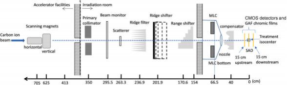
Fig. 1. The construction and physical geometry dimension of the carbon ion facility and the setup of CMOS and films in this study.
2.1. Experiment setup in the treatment room
In this study, an IMP(Institute of Modern Physics) home-made large-format OmniVision (Shanghai, China) model OV9712 and Aptina (ON Semiconductor, Phoenix, AZ, USA) model AR0130 COTS CMOS active pixel sensors (APSs) were used as an FWHM detector for measurement in carbon scanning-passive scatter beam measurement. The CMOS COTS digital sensors are energy independent and can be used for particle counting up to a radiation dosage of 51.24 Gy after good calibration of linearity and reproducibility to reduce background noise. The CMOS COTS sensors. The large-format CMOS sensor was set up on the treatment couch in the air with the detector front face perpendicularly to the carbon ion beam at the nominal source-axis-distance (SAD) as well as upstream at 20 cm, 40 cm, and 50 cm; and downstream at 10.4 cm from the SAD (in Fig. 2).
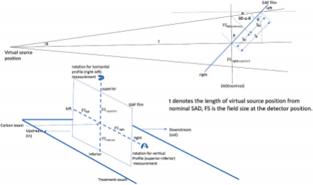
Fig. 2. The Half Width Half Maximum (c-HWHM) Tilting Angle Convergent Method for Determining the Virtual Source Position of Scanning Beam in Carbon Ion Therapy.
2.2.The FWHM measurement with the CMOS sensor and the GAFEBT 3 film
The large-format CMOS sensor was placed on the treatment couch with the detector’s frontal face vertically face to the horizontal beam line. All five energy of carbon ion beams could be evaluated during this investigation.
The large-format CMOS signals were in pixels and the Gaf Chromic EBT3 films (Ashland Specialty Ingredients GP, NJ USA; Lot # 04022002, Exp. Date: April 2023) were adopted for the dose profile measurement in determining the virtual source position for this study. The dose profile of the exposed film was processed following international protocols (Dreindl et al., 2014). Films were subjected to a pre-exposure technique to reduce the uncertainty in deriving the calibration curve (Kamomae et al., 2011). A priming dose of 2 Gy was given with the carbon ion energy of 330 MeV/u for each film to homogenize the film density. The film’s homogeneity was then measured with a densitometer.
2.3.Derivation of horizontal and vertical magnets-driven dose profile to get the FWHM
The FWHM of dose profiles measured by the large-format CMOS detectors were mainly adopted for the virtual source position study. All exposed films of the desired field size were then scanned with an Epson Expression 11000XL scanner in the 72 dpi mode (0.353 mm per dot interval), and the data were saved as tagged imagefile format (TIFF) and analyzed by the filmQA Pro v7(Ashland, USA) imaging procession software. A red filter was placed on top of the GAF films for raising the resolution ofthe dose-OD curves before scanning to increase the slope of the H-D curve (García-Garduno et al., 2016).
2.4.Determine the horizontal nozzle virtual source position by back-projecting the various source-film-distance FWHM to zero
To determine the horizontal nozzle’s virtual source position by back projecting the various source-film distance FWHM from downstream to upstream to zero, the procedures were:
Firstly, plot the FWHM versus the offset, the distance upstream and downstream from the nominal SAD, based on the film setup in Fig. 1. Secondly, derive the linear regression (y = a x + b,y denotes FWHM,x is the offset in the film set up in Fig. 2) from the curves created by the FWHM versus the offset given by the location of the film with no tilting setup. The virtual source position,x, can be derived by letting y be zero, which means the virtual source position is identified from the back projecting method when the FWHM is zero.
2.5.Determine the horizontal nozzle virtual source position by the half width half maximum tilting angle convergent method at the various source-film-distance
The experimental setup of the full-width half maximum tilting angle convergent method was displayed in Fig. 2, t denotes the assumed length of virtual source position from nominal SAD, FS right, and FS left (or FS superior and FS inferior) are the profile of field size where it was measured in the horizontal direction (right-left) or vertical direction (superior-inferior), respectively. The tilting angle, θ, was rotating the film or the CMOS detector’s face with a vertical axis clockwise in Fig. 2.
In Fig. 2, the clockwise rotation angle of the film/CMOS’s front face with the vertical axis is θ, while the angle, α, denotes if the FWHMs at downstream or upstream were diverged with this unique angle, another word, the exact virtual source position has been identified.
In Fig. 2, the derivation of α, please refer to Fig. 2.
This method was based on the calculation of angle α, the angle α will converge to a unique value when an assumed virtual source position,t, is given to all different distances in any carbon ion energy and field sizes. Here, t+0, denotes the distance of assumed virtual source position to nominal SAD is t, and t-20 denotes the distance of assumed virtual source position to upstream point at 20 cm is t-20 et al. for upstream at 40 cm; t+10.4 denotes the distance of assumed virtual source position to downstream point at 10.4 cm is t+10.4 cm.
The results of the virtual source position calculated by the half width half maximum tilting angle convergent method were compared with the results of the conventional FWHM back projecting to zero methods.
3.Results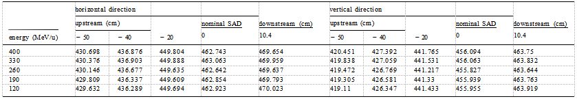 Table 1 The FWHM of horizontal and vertical direction dose profile measured by the large-format CMOS detectors in carbon ion therapy.
Table 1 is the FWHM of horizontal and vertical direction dose profiles measured by the large-format CMOS detectors and Gaf chromic films in carbon ion therapy.
The film’s dose profile FWHM for all carbon ion energies had been spot compared with CMOS, and the results were within 1.5%.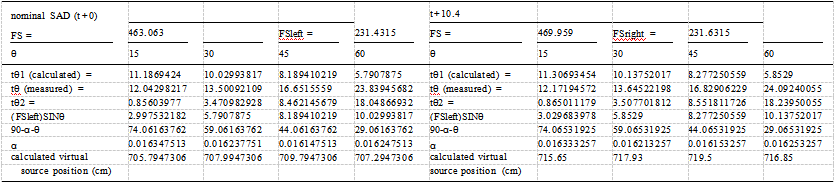 Table 2 The calculation of α with different rotation angle θ at nominal SAD (t+0), t+10.4, t-20, t-40 in the horizontal direction of carbon ion energy 330 MeV/u
Table 2 is the calculation of α with different rotation angles θ at nominal SAD (t+0), downstream (t+10.4), upstream (t-20), and upstream (t-40) in the horizontal direction of carbon ion energy 330 MeV/u, respectively.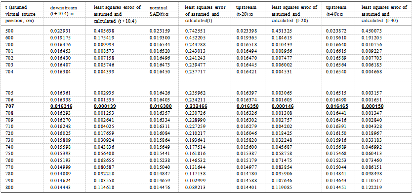 Table 3 The least squares error of calculated angle α in the horizontal direction (right-left) with the actual α driven by an assumed virtual source position, t in the different upstream and downstream distances in carbon ion energy 330 MeV/u. The virtual source position is converged with the smallest least squares error to a distance of 707 cm (with bold and underlined in the table).
Table 3 presents the comparison of the tilting angle method, α by the arcTAN method, α by calculating with no tilting angle θ in the horizontal direction (right-left) with an assumed virtual source position, t, at the different upstream and downstream offsets in carbon ion energy 330 MeV/u. The virtual source position is found where the smallest least squares error, αtilting method -αarcTAN method, happens of all t+ 10.4,t,t-20, and t-40 at a point of 707 cm (with bold and underlined in the table).
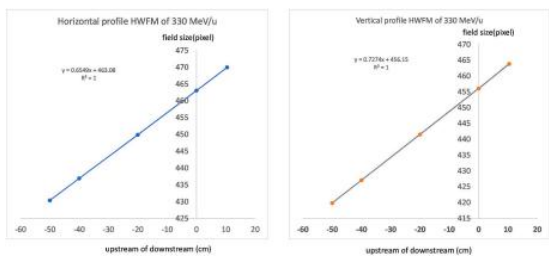
Fig. 3. The linear regression from the curves created by the FWHM versus nominal distance of horizontal direction (left) and vertical direction (right) in the carbon ion energy of 330 MeV/n. (y = ax + b, y denotes FWHM, x is the virtual source distance in the film setup geometry in Fig. 1).
Fig. 3 presents the linear regression from the curves created by the FWHM versus the nominal distance of horizontal direction (left) and vertical direction (right) in the carbon ion energy of 330 MeV/n. (y = ax + b, y denotes FWHM, x is the virtual source distance in the film setup geometry in Fig. 1).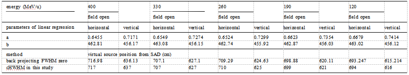 Table 4 The virtual source position derived by cHWFM method and back projecting FWHM zero method in the linear regression y = ax + b with the parameters a, and b for each carbon ion energy at horizontal and vertical direction.
Table 4 presents the virtual source position derived by the cHWFM method and back projecting FWHM zero method in the linear regression y = a x + b with the parameters a, and b for each carbon ion energy at the horizontal and vertical directions.
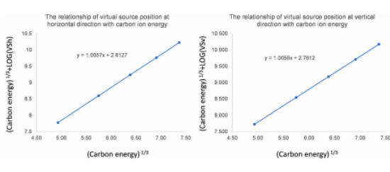
Fig. 4. The distance of virtual source position of the carbon ion beam in the horizontal and vertical directions can be integrated as a function of carbon ion energy in Equations 1 and 2, respectively.
VSh = 0.0057×10 source position in the horizontal direction, E means the virtual source position at this energy of carbon ion beam.
VSv = 0.0055×10 source position in the vertical direction, E means the virtual source position at this energy of the carbon ion beam.
The distance of the virtual source position of the carbon ion beam in the horizontal and vertical direction can be integrated as a function of carbon ion energy in Equations 1 and 2, respectively in Fig. 4.
4.Discussion
Unlike the X-rays generated from a linear accelerator, a carbon ion beam does not emanate from a physical source in the accelerator head. The point called the virtual source of the electron beam is a pencil electron beam passing through the bending magnets, scattering foils, and monitor chambers in the head of the accelerator, and is spread into a sufficient clinical available field size that appears to originate from this so call virtual source point. Measurements of the virtual source position of the electron beam can use the inverse square law method by the reading of the ion chamber to correct the dose output as a function of the air gap between the electron applicator end and the measurement position. In the carbon ion beam, the inverse square law method is no longer used since the percent depth dose of the carbon ion beam is just the reverse of electron beam’s percent depth dose which is well known as the plateau-Bragg peak curve.
There are few studies regarding the measurement of virtual source position on heavily charged particles. A cross-profile measurement of the proton fluency in the air at different positions from the isocenter was studied for determining the proton virtual source position (Schaffner, 2008).
Despite several methods that have been suggested for the determination of the virtual source position in electrons, the virtual source point of a carbon ion beam has never been investigated. The measurement of virtual source position in the carbon ion beam, nevertheless, can use the setup like in electron using the field size on film along the beam axis downstream to upstream back projecting to a point convergently of zero field size as the intersection point of the source.
The field size provided by the carbon ion beam in our facility in room 2 is a scanning-passive scatter type in Fig. 1 which is rather than abroad beam like the electron, thus, the virtual source point needs to be investigated separately in the horizontal (x direction) and vertical (y direction) of the beam profiles driven by horizontal and vertical magnets using the back projections of the 50% width to zero at different measurement distances.
The technique developed for carbon ion beam delivery in our facility for room 2 is scanning-passive scattering. In this approach, unlike the beam that is spread using scatter foils, the delivery of scanning-passive scattered beams of our carbon ion beams was formed by thousands of narrow and quasi-monoenergetic carbon pencil-like beams directed by horizontal magnetism first and then pass a vertical magnetism to form a full field size for clinical use.
The FWHM of the profile in the horizontal direction and in the vertical direction for each energy are shown in Table 1. The unit of FWHM in the horizontal and vertical direction in the dose profile measured by the large-format CMOS detectors was in pixel, a pixel equals 0.5 mm, therefore, the field size of carbon ion energy 330 MeV/u at the nominal SAD was 231.53 mm by 231.92 mm in the horizontal and vertical directions as shown in Table 1, respectively.
Table 2 demonstrates the value α calculated by cHWFM method with the distance of the assumed virtual source position in the horizontal direction, t+0 (the distance of the assumed virtual source position point to nominal SAD), t+10.4 (the distance of the assumed virtual source position point to nominal SAD + 10.4 cm downstream),t -20 (the distance of assumed virtual source position point to nominal SAD - 20 cm upstream), t -40 (the distance of assumed virtual source position point to nominal SAD - 40 cm upstream) of carbon ion energy 330 MeV/u.
The calculated angles α by tilting method at every tilting angle θ, α at tilting angle θ of 15◦, 30◦, 45◦, 60◦, coincidences with a unique angle of α of the tilting angle θ at different t, t+10.4, t-20, t-40.
For example, the calculated angles α of tilting angle θ 30◦ at t, t+10.4, t-20, t-40 refer to 0.01623, 0.01621, 0.01622, 0.01623, and its calculated virtual source positions are 707.9 cm, 717.9 cm (707.5 cm + 10.4 cm), 688.1 cm (708.1 cm–20 cm), 668.1 cm (708.1 cm–40 cm), respectively. Where this 707.9 cm, 707.5 cm, 708.1 cm, and 708.1 cm are calculated as virtual source positions. The precise virtual source position is found where the smallest least squares error, αtilting method -αarcTAN method, happens of all t+ 10.4,t,t-20, and t-40 at a point of 707 cm (with bold and underlined in Table 3).
Table 2 demonstrates the determination of the virtual source position using calculated angles α by tilting method at every tilting angle θ in the horizontal direction of scanning-passive scattered beams for 330 MeV/u beam energy, and so forth for determining the virtual source position极 using the same procedures for other carbon ion energies.
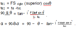
The method of the convergent arcTAN in Table 3 was calculated by the following equation to get α,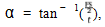 , denotes the assumed length of the virtual source position from nominal SAD, and FS is the field size at the detector position. This method was based on the calculated arcTAN angle α, α will converge to a unique value in arcTAN calculation when an assumed virtual source position of
 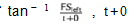 (the distance of assumed virtual source position point to nominal SAD + 10.4 cm downstream), t-20(the distance of assumed virtual source position point to nominal SAD -20cmupstream)
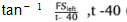 (the distance of assumed virtual source position point to nominal SAD -40cmupstream),
The result can be used to check the virtual source position calculated by the back projection zero methods and the cHWHM method.
The detailed process of the arcTAN method for determining the virtual source position in the horizontal direction of the scanning-passive scatter beam in 330 MeV/u carbon ion therapy was listed in Table 3. The least squares error calculated at nominal SAD, downstream 10.4 cm, upstream 20 cm, and upstream 40 cm were 0.000139, 0.000141, 0.000146, and 0.00015, respectively. The smallest least squares error indicates the actual virtual source position, t, is at 707 cm in Table 3.
The error caused by the accuracy of the digital reader in films or the resolution of CMOS, and even the error of precise position caused by manual setup is inevitable. We test the variation of virtual source position accuracy by changing the HWFM intentionally from 极1 mm step by step to 10 mm in Table 2 on every tilting angle θ, and the calculated virtual source position varies from 703 cm to 677 cm, however, the least squares error remains with a convergent α calculated method in Table 2 at 707 cm as shown in Table 3. The cHWFM method plays an important role to eliminates the unavoidable manual setup error and machine limitation in determining the virtual source position for carbon ion beams.
Fig. 3 shows the parameters a and bin the linear regression when y = 0, y denotes field size in y = a x + b, which means the virtual source position, x, happens at the back projection point when the field size becomes zero. The virtual source position derived by the cHWFM method was also listed in Table 4 for comparison with the results derived by back-projecting HWFM to zero methods.
The solution of x, in y = a x + b, the parameters a, and b listed in Table 4 were generated by the same process of back projecting HWFM to zero methods to get the virtual source position for every energy.
The virtual source position for higher carbon ion energy has an obviously longer distance from the SAD since the more energy of the carbon ion beam, the less bending affected by the horizontal and vertical magnetic deflection, therefore, virtual source positions from SAD are decreased from high to low carbon ion energy which was shown in Table 4.
The distance of the virtual source position of the carbon ion beam in the horizontal and vertical direction can be integrated as a function of carbon ion energy in Equations 1 and 2, respectively in Fig. 4. The virtual source position in the horizontal direction can be presented by VSh, where.
VSv = 0.0055 ᆞ10 (E 1 3 + 2.7162),
VSv denotes the virtual source position in the vertical direction, E means the virtual source position at this energy of the carbon ion beam.
The relationship of the virtual source position and carbon ion energy in the horizontal and vertical directions are generated in equations 1 and 2. The comparison of calculation and measurements are agreed upon within 1%. As previous discussion in the manuscript, the virtual source position dominates the carbon ion beam dosimetry calculation inside the human (or phantom) and the accuracy of multi-leaf collimator (MLC) opening. We have to investigate the virtual source position without having any absorber or measuring inside the phantom. The dosimetric characteristics of step-by-step Linear Energy Transfer (LET) inside the human body of carbon ion passive-scatter beams. For the majority of clinical situations, not only the LET for dose calculation but also the field size opened by the Multi-Leaf Collimator of passive-scatter design was influenced significantly by the virtual source position in carbon ion beams. This study is to remedy a defect of no investigation for the virtual source position of carbon ion beams. The MLC opening was corrected according to the measured virtual source position for every carbon ion energy in the horizontal and vertical directions. Furthermore, the MLC opening depends not only on the accuracy of the virtual source position but also depends on whether the MLC offset is carefully adjusted (Wu et al., 2012). The fabrication of a precise compensator for modulating the SOBP is also counted on the measured virtual source position.
5.Conclusion
The study of virtual source position in carbon ion beams is rare, and we have developed an innovative technique capable of dealing with the virtual source position delivered by different carbon ion energies from scanning-passive scatter beams in our facility. The cHWFM method for determining the virtual source position eliminates the unavoidable manual setup error and machine limitation in the conventional back projecting HWFM method. The method for investigating the virtual source position in carbon ion beams can be applied to proton beams and electron beams in the next study.
The calculation of radiation doses may not always be in agreement for MLC treatment fields at a carbon ion beam treatment planning system unless the virtual source position and MLC offset are well-calibrated. The expansion of this method to incorporate these effects as well as in pencil scanning beam is possible and is currently being addressed.
Declaration of competing interest
The authors declare the following financial interests/personal relationships which may be considered as potential competing interests:
There are no actual or potential competing interests in this study. This manuscript has not been published nor concurrently submitted for publication elsewhere.
Data availability
Data will be made available on request.
Acknowledgements
The author appreciates Professor Yan-Shan Zhang for his great contribution to this study. Professor Yan-Shan Zhang is juxtaposed with the first author (co-first author with equal contribution). Ye Yan Cheng for his great contribution to this study. Professor Ye Yan Cheng is juxtaposed with the correspondence author (co-correspondence author with equal contribution).
This study was supported by the foundation of the nature science project of Gansu province, China (23JRRH0006).
This work was supported by Funding: Overseas high professional experts introduced projects of the Science and Technology Department, Gansu Province, China. (The clinical application of carbon ion beams in radiation oncology 22JR10KA029).
This work was supported by the Funding: Central government Guided Local fund projects of the Science and Technology Department of Gansu Province, China. (The Precise therapy platform of clinical and research for radiation oncology in carbon ion therapy 22ZY1QH001).
References
Bortfeld, T., Schlegel, W., 1996. An analytical approximation of depth–dose distributions for therapeutic proton beams. Phys. Med. Biol. 41 https://doi.org/10.1088/0031-9155/41/8/006, 1331–9.
Dreindl, R., Georg, D., Stock, M., 2014. Radiochromic film dosimetry: considerations on precision and accuracy for EBT2 and EBT3 type films. Med. Phys 24 (2), 153–163. https://doi.org/10.1016/j.zemedi.2013.08.002.
García-Garduno, O.A., Lrraga-Gutirrez, J.M., Rodríguez-Villafuerte, M., 2016. Effect of correction methods of radiochromic EBT2 films on the accuracy of IMRT QA. App. Radi. Isot 107, 121–126. https://doi.org/10.1016/j.apradiso.2015.09.016.
Gottschalk, B., Koehler, A.M., Schneider, R.J., 1993. Multiple Coulomb scattering of 160 MeV protons. Nucl. Instrum. Methods Phys. Res. B 74, 467–490. https://doi.org/10.1016/0168-583X(93)95944-Z.
Jamshidi, A., Kuchnir, F.T., Reft, S.C., 1986. Determination of the source position for the electron beam from a high-energy linear accelerator. Med. Phys. 13, 942. https://doi.org/10.1118/1.595823.
Kamomae, T., Miyabe, Y., Sawada, A., 2011. Simulation for improvement of system sensitivity of radiochromic film dosimetry with different band-pass filters and scanner light intensities. Radiol. Phys. Technol. 4 (2), 140–147. https://doi.org/10.1007/s12194-011-0113-6.
Khan, F.M., Sewchand, W., Levitt, S.H., 1978. Effect of air space on depth dose in electron beam therapy. Radiology 126, 249. https://doi.org/10.1148/126.1.249.
Kimstrand, P., Traneus, E., Ahnesjo, A., 2007. A beam source model for scanned proton beams. Phys. Med. Biol. 52, 3151–3168. https://doi.org/10.1088/0031-9155/52/11/015.
Kooy, H., Schaefer, M., Rosenthal, S., 2003. Monitor unit calculations for range-modulated spread-out Bragg peak fields. Phys. Med. Biol. 48, 2797–2808. https://doi.org/10.1088/0031-9155/48/17/305.
Kooy, H., Rosenthal, S., Engelsman, M., 2005. The prediction of output factors for spread-out proton Bragg peak fields in clinical practice. Phys. Med. Biol. 50, 5847–5856. https://doi.org/10.1088/0031-9155/50/24/006.
Meyer, J.A., Palta, J.R., Hogstrom, K.R., 1984. Determination of relatively new electron dosimetry measurement techniques on Mevatron 80. Med. Phys. https://doi.org/10.1118/1.595550, 11:670. 43.
Petti, P.L., 1992. Differential-pencil-beam dose calculation for charged particles. Med. Phys. 19, 137–149. https://doi.org/10.1118/1.596887.
Petti, P.L., 1996. Evaluation of a pencil-beam dose calculation technique for charged particle radiotherapy. Int. J. Radiat. Oncol. Biol. Phys. 35, 1049–1057. https://doi.org/10.1016/0360-3016(96)00233-7.
Russell, K.R., Isacsson, U., Saxner, M., 2000. Implementation of pencil kernel and depth penetration algorithms for treatment planning of proton beams. Phys. Med. Biol. https://doi.org/10.1088/0031-9155/45/1/302, 45 9–27.
Schaffner, Barbara, 2008. Proton dose calculation based on in-air fluence measurements. Phys. Med. Biol. 53, 1545–1562. https://doi.org/10.1088/0031-9155/53/6/003.
Shroder-Babo, P., 1983. Determination of the virtual electron source of a betatron. Acta Radiol 364 (Suppl. l), 7–42. PubMed ID 6316743. https://www.ebi.ac.uk/europepmc/webservices/rest/search?query=EXT_ID:6316743%20AND%20SRC:MED&resulttype=core&format=json.
Wu, Jia-Ming, Lee, Tsair-Fwu, Kuo, Chung-Ming, 2012. A light field-based method to adjust rounded leaf end MLC position for split shape dose calculation correction in a radiation therapy treatment planning system. J. Appl. Clin. Med. Phys. 13 (6), 3–18. https://doi.org/10.1120/jacmp.v13i6.3937
Preliminary Review: Zhang Lihong Final Review: Zhang Jie