
The determination of virtual source position using convergent arcCOS method for scanning-passive sca
The determination of virtual source position using convergent arcCOS method for scanning-passive scatter beam in carbon ion therapy
Y. Qi1#, Y-S. Zhang1#, Y-C. Ye1#, T-F. Lee3, J-M. Wu1,2,4#
1Heavy Ion Center of Wuwei Cancer Hospital, Gansu Wuwei Academy of Medical Sciences, Gansu Wuwei Tumor Hospital, Wuwei city, Gansu province, China
2Department of Medical Physics, Chengde Medical University, Chengde City, Hebei Province, China
3Medical Physics and Informatics Laboratory of Electronic Engineering, National Kaohsiung University of Science and Technology, Kaohsiung 80778, Taiwan
4Department of Radiation Oncology, Yee Zen General Hospital, Tao Yuan City, Taiwan
ABSTRACT
Background: We developed a convergent arcCOS (cACOS) technique capable of dealing with the virtual source position delivered by different carbon ion energies from the pattern of scanning-passive scatter beam in this study. Materials and Methods: A homemade large-format CMOS sensor and Gaf Chromic EBT3 films were used for the virtual source position measurement. The Gaf films were embedded in a self-designed rectangular plastic frame to tighten the films and set up on a treatment couch for irradiation in the air with the film perpendicular to the carbon ion beam at the point of nominal source-axis-distance (SAD) as well as upstream and downstream from the SAD. The horizontal carbon ion beam with 5 energies at a machine opening field size was carried out in this study. The virtual source position was determined with a convergent arcCOS method and compared with the linear regression by back projecting the FWHM to zero at a distance upstream from the various point of source- film distance. Results: The determination of virtual source position using convergent arcCOS method agrees with the method by back projecting the FWHM to zero, and for higher carbon ion energy has an obvious longer distance from the SAD since the more carbon ion beam energy, the less spreading affected by the horizontal and vertical magnetism, therefore, the distance of virtual source positions is decreased from SAD with high to low energy. Conclusion: We have developed a technique capable of dealing with the virtual source position with a convergent arcCOS method to avoid any manual measurement mistakes in scanning-passive scatter carbon ion beam. The method for investigating the virtual source position in the carbon ion beam in this study can also be used for external electrons and the proton.
INTRODUCTION
The carbon ion beam, unlike an electron beam from a linear accelerator, does not emanate from a physical point source in the nozzle acceleration system (1-4). A narrow energy-dependent spot size of the carbon ion beam, after passing through the horizontal and vertical scanning magnets in the vacuum window of the accelerator, primary collimator, beam monitor, spreading scatterer, ridge filter and ridge shifter, and range shifter, is scanned spreading into a broader two-dimensional field that appears to diverge from a point. This point is known as the virtual source position (5), which may be defined as an intersection point of the back projection along with the most probable directions of carbon ions motion at a fixed position, for example, on the plane at a nominal source-axis-distance. There are many investigations describing the method of determining the virtual source position by inverse square law correction for output at extended source-skin-distance (SSDs) under all clinical conditions or by field size magnification on film with distance (6-9). Despite a lot of methods that have been proposed for the determination of virtual source position for electron beam therapy in a linear accelerator and proton beam, none for heavy charged particles-like carbon ions have been investigated (10-11). Usually, the virtual source point needs to be measured by the back-projection of the 50% width of the beam profiles acquired at different distances upstream or downstream of the source in external electron therapy (12). In our facility, a certain beam field size without the collimation of multi-leaves collimator (MLC), the largest field size was used for measurements in this study. The measurement of virtual source position for carbon ion beams was unusual than in electron beam therapy, the measurement of virtual source position cannot apply by inverse square law correction from chamber output at extended SSDs since no inverse square response is available for the chamber along the carbon beam’s percent depth dose curve on the plateau at different distances.
The Institute of Modern Physics (IMP) was founded in 1957 in Lanzhou, China. The National Laboratory of Heavy Ion Accelerator, Lanzhou (NLHIAL) was established at IMP in 1991 to take the advantage of full usage of the research facilities at IMP (8). WuWei Heavy Ion Center, Wuwei Cancer Hospital, GanSu, China (WHICH) consists main synchrotron ring to accelerate sufficient particle energy and flux for four treatment rooms used- room 2, equipped with a horizontal, and a vertical nozzle aimed at one isocenter with scanning-passive scatter beam, was adopted for the virtual source position study. The importance of the virtual source position not only fits the need of correcting the opening of the multi-leaf collimator in field sizes but also supports the fabrication of compensators for carbon ion therapy for patient-specific dosimetric calculation in the treatment planning system.
The virtual source position for carbon ion beams of energies 120, 190, 260, 330 MeV/u, and 400 MeV/u in the WHICH have been measured. It is realized that the virtual source position’s issue in the electron beam is highly energy-dependent, therefore, if the issue is also highly energy and field size-dependent for the carbon ion beam then the virtual source position needs to be measured carefully for each nozzle.
The dosimetric characteristics of step-by-step Linear Energy Transfer (LET) inside the human body of carbon ion passive-scatter beams generated by IMP cyclotron-synchrotron accelerators depending on the horizontal and vertical scanning magnets in the vacuum window of the accelerator, primary collimator, beam monitor, spreading scatterer, ridge filter, and ridge shifter, and range shifter. For the majority of clinical situations, not only the LET for dose calculation but also the field size opened by Multi-Leaf Collimator of passive-scatter design was influenced significantly by the virtual source position in carbon ion beams. This study is to remedy a defect of no investigation for the virtual source position of carbon ion beams.
MATERIALS AND METHODS
The virtual source position was intended to be determined with the conventional back projecting zero methods and was double-checked additionally by the convergent arcCOS method to minimize mistakes caused by manual measurement by exposing a certain field on Complementary Metal Oxide Semiconductor (CMOS) sensor and films in the air with an interval of some distance upstream and downstream from nominal source-axis distances for beam profiles analysis.
A horizontal beam equipped in room 2 was adopted for the effective source position measurement in this study, the construction and physical geometry dimension of our carbon ion facility is shown in figure 1. The carbon ion beam passes a horizontal magnet scanning at x direction beam first and then through to a vertical magnet scanning at y direction beam to create the scanned x-y field size for clinical use. The ridge filter, ridge shifter, and range shifter, as well as compensator, were removed with only the primary collimator opened during the measurement in this study.
The carbon ion with an initial energy of 120 MeV/u to 400 MeV/u in an increasing interval of 70 MeV/u and field sizes set by the horizontal-vertical magnets at a machine opening field size was carried out for the measurements of the virtual source position at our institute in this study. The distance between the 50% of the central axis value from the profiles was measured and denoted as the full width half maximum (FWHM). The FWHM was measured and plotted as a reciprocal profile using the measurement of the machine opening field with different distances measured upstream or downstream within 50cm from the SAD.
The linear relationship of the beam’s FWHM in the air appears to diverge geometrically from a point source where the beam width is 0 when projecting these lines back to the central axis. On the contrary, the angle of arcCOS at each different field size and its relative virtual source position converges to one unique value when an exact assumed virtual source position is given. The virtual source position using the convergent arcCOS method can be used to double-check with the back projecting zero methods to avoid any manual measurement mistakes in the scanning-passive scatter carbon ion beam.
Experiment setup in the treatment room
In this study, an IMP home-made large-format OmniVision (Shanghai, China) model OV9712 and Aptina (ON Semiconductor, Phoenix, AZ, USA) model AR0130 COTS CMOS active pixel sensors (APSs) were used as an FWHM detector for measurement in carbon scanning-passive scatter beam measurement. The CMOS COTS digital sensors are energy independent and can be used for particle counting up to a radiation dosage of 51.24 Gy after good calibration of linearity and reproducibility to reduce background noise. The CMOS COTS sensors. The large-format CMOS sensor was set up on the treatment couch in the air with the detector perpendicular face to the carbon ion beam at the nominal source-axis-distance (SAD) as well as upstream at 20cm, 40cm, and 50cm and downstream at 10.4 cm from the SAD in figure 1.
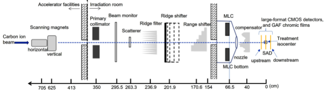
Figure 1. The construction and physical geometry dimension of carbon ion facility and film setup in this study.
Gaf Chromic EBT3 films were used to double checking with CMOS profiles. Gaf Chromic EBT3 films were embedded in a self-designed rectangular plastic frame to tight the films and set up on the treatment couch in the air with the film perpendicular to the carbon ion beam at the nominal source-axis-distance (SAD) as well as upstream and downstream 20 cm from the SAD in figure 1. Both the measurement of CMOS and the Gaf Chromic EBT3 film in horizontal carbon ion beam with 5 energies at a maximum field size of 231.875 mm × 234.827mm for the measurements of virtual source position was carried out in this study.
The FWHM measurement with the CMOS sensor and the GAFEBT3 film
The large-format CMOS sensor was placed on the treatment couch with the detector frontal face to the horizontal nozzle, corresponding to the beam entering from the top (front face) of the detector. All five energy of carbon ion beams could be evaluated during this investigation.
The large-format CMOS signals were in pixels and the Gaf Chromic EBT3 films (Ashland Specialty Ingredients GP, NJ USA; Lot # 04022002, Exp. Date: April 2023) was adopted for the dose profile measurement in determining the virtual source position for this study. The dose profile of exposed film was processed following international protocols(13). Films were conducted with a pre-exposure technique to reduce the uncertainty in deriving the calibration curve (14).
Derivation of horizontal and vertical magnets driven dose profile to get the FWHM
The FWHM of dose profiles measured by the large-format CMOS detectors were mainly adopted for the virtual source position study. All exposed films of the desired field size were then scanned with an Epson Expression 11000XL scanner in the 72dpi mode (0.353 mm per dot interval), and the data were saved as tagged image file format (TIFF) and analyzed by the filmQA Pro v7(Ashland, USA) imaging procession software. A red filter was placed on top of the GAF films for raising the resolution of the dose-Optic Density curves before scanning to increase the slope of the H-D calibration curves (15).
Determine the horizontal source position by back projecting the distance between FWHM for the various source-film-distance
Firstly, plot the FWHM versus nominal distance curves for every SAD, upstream, and downstream based on the film setup geometry in figure 1 Secondly, derive the linear regression, y denotes FWHM, a and b is the parameters regressed by the experiment results from the films, and x is the virtual source position from the nominal SAD shown in figure 1 from the curves created by the FWHM versus nominal distance.
y=a x + b (1)
Thirdly, let y=0 then the virtual source position can be derived from b divided by a, negative value denotes the virtual source position is upstream from SAD toward carbon ion source point.
Determine the horizontal nozzle virtual source position by the convergent arcCOS (cACOS) method at the various source-film-distance
The method of convergent arcCOS (cACOS) was displayed in figure 2 with the equation of, t denotes the assumed length of the virtual source position from nominal SAD, and FS is the field size at the detector position. This method was based on the angle α of arcCOS, α will converge to a unique value in the arcCOS calculation when an assumed virtual source position, t is given to all different upstream of downstream distances.
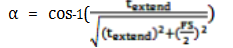 (2)
(2)
The virtual source position was then calculated by the converged arc COS method with the assumed virtual source position, t, in t at nominal SAD, tupstream with upstream distances at 20cm, 40cm, 50cm, and tdownstream with downstream distances at 10.4cm.
Uncertainties in the virtual source position measurements by the back projecting and convergent arcCOS (cACOS) methods
The overall uncertainty in the virtual source position measurements of the specified field size measured on films is given by the alignment errors in the setup accuracy upstream or downstream from the point of SAD. Alignment errors of the films are estimated to lead to a disorder regulation of virtual source position. To archive, the accuracy of the data collection, all measurements including the experimental setup and film processing were repeated three times to eliminate the uncertainty caused by manual and device errors.
SPSS 20.0 was used to analyze the measurement data on films of HWFM. The measurement was expressed by mean ± SD (1 standard deviation) or by percentage. The potential risk factors for the virtual source position were analyzed by using the single factor chi-square test and logistics regression model, and the difference was considered statistically significant with P<0.05.
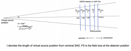
Figure 2.The convergent arcCOS method for determining the virtual source position of scanning-passive scatter beam in carbon ion therapy.T extend denotes the measurement distance tat upstream,downstream,or without extend at nominal SAD.
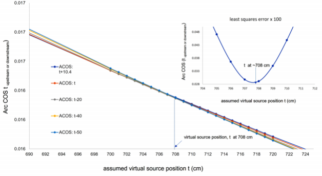
Figure 3.The converged arcCOS method for determining the virtual source position in horizontal direction of scanning-passive scatter in 330 MeV/u beam in carbon ion therapy.
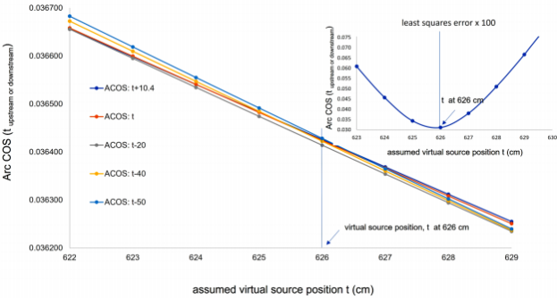
Figure 4.The converge arcCOS method for determining the virtual source position in vertical direction of scanning-passive scatter in 330 MeV/u beam in carbon ion therapy.
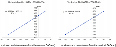
Figure 5. The linear regression from the curves created by the FWHM versus nominal distance in the carbon ion energy of 330 MeV/n. (y=ax+b, y denotes FWHM, x is the virtual source distance in the film setup geometry in figure 1).
Table 1.The FWHM of horizontal and vertical direction dose profile measured by the large-format CMOS detectors in carbon ion therapy
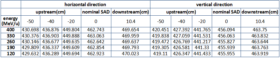
Note:HWFM unit in pixel.The overall uncertainty for the reproducibility specified FWHM amounts to 1%,
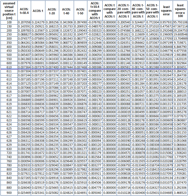
Table 2.The convergent arcCOS method for determining the virtual source position in horizontal direction of scanning-passive scatter in 330 MeV/u beam energy in carbon ion.
Note:The assumed virtual source position can be detailed to 0.1 cm,and the film FWHM measurement error of 0.5 mm (the large-format CMOS detectors were in pixels,a pixel equals 0.5mm) leads to 1x10⁻³% deviation of α(ACOS) at every t extend.The overall uncertainty for the reproducibility of calculated virtual source position in the vertical direction by the assumed value of t amounts to 0.1%.
Table 3.The converge arcCOS method for determining the virtual source position in vertical direction of scanning-passive scatter in 330 MeV/u beam in carbon ion therapy
Note:The assumed virtual source position can be detailed to 0.1 cm,and the film FWHM measurement error of 0.5 mm (the large-format CMOS detectors were in pixels,a pixel equals 0.5mm) leads to 1x10⁻³% deviation of α(ACOS) at every t extend.The overall uncertainty for the reproducibility of calculated virtual source position in the vertical direction by the assumed value of t amounts to 0.1%.
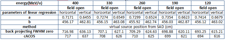
Table 4.The parameters a,and b of the linear regression y=a x +b,and the virtual source position derived by back projecting FWHM zero method and the cACOS method for each carbon ion energy in the horizontal and the vertical directions.
Note: The errors of calculated virtual source position by assumed t extend with back projecting FWHM to zero methods were
within 1.1 ± 0.001, p = 0.033.
RESULTS
Figure 2 the convergent arcCOS method for determining the virtual source position of scanning-passive scatter beam in carbon ion therapy. Textend denotes the measurement distance t at upstream, downstream, or without extend at the point of nominal SAD.
Figure 3 is the converged arcCOS method for determining the virtual source position in the horizontal direction for scanning-passive scatter in 330 MeV/u beams in carbon ion therapy.
Figure 4 is the converge arcCOS method for determining the virtual source position in the vertical direction for scanning-passive scatter in 330 MeV/u beams in carbon ion therapy.
Figure 5 is the linear regression from the curves created by the FWHM versus nominal distance in the carbon ion energy of 330 MeV/n. (y=ax+b, y denotes FWHM, x is the virtual source distance in the film setup geometry in figure 1)
Table 1 is the FWHM of horizontal and vertical direction dose profiles measured by the large-format CMOS detectors in carbon ion therapy. The overall uncertainty for the reproducibility specified FWHM amounts to 1%, averaging 4.5 pixels. Films dose profile FWHM for all carbon ion energies had been compared with CMOS, and the results were within 1.5%.
Table 2 demonstrates the convergent arcCOS method for determining the virtual source position in the horizontal direction of scanning-passive scatter in 330 MeV/u beams in carbon ion therapy. The angle α of the arcCOS in the horizontal direction with its relative assumed virtual source position will become a unique value with all α deviation converging to a minimum value of a distance of 708 cm (table 2) from downstream to upstream. The assumed virtual source position can be detailed to 0.1 cm, and the film FWHM measurement error of 0.5 mm (the large-format CMOS detectors was in pixel, a pixel equals 0.5mm) leads to 1×10⁻³ % deviation of α (ACOS) at every textend. The overall uncertainty for the reproducibility of calculated virtual source position in the horizontal direction by the assumed value of t amounts to 0.1%.
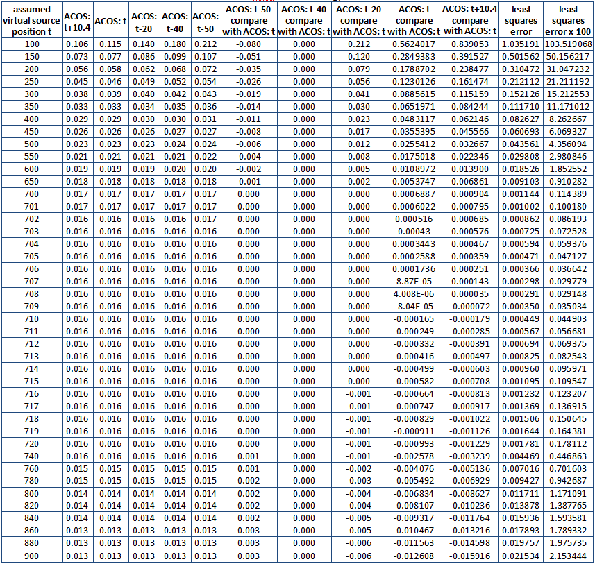
Table 3 is the converge arcCOS method for determining the virtual source position in the vertical direction of scanning-passive scatter in 330 MeV/u beams in carbon ion therapy. The angle α of the arcCOS in the vertical direction with its relative assumed virtual source position will become a unique value with all α deviation converging to a minimum value of a distance of 626 cm (with bold and underlined in table 3) from downstream to upstream. The assumed virtual source position can be detailed to 0.1 cm, and the film FWHM measurement error of 0.5 mm (the large-format CMOS detectors was in pixel, a pixel equals 0.5mm) leads to 1x10⁻³ % deviation of α(ACOS) at every textend. The overall uncertainty for the reproducibility of calculated virtual source position in the vertical direction by the assumed value of t amounts to 0.1%.
Table 4 lists the parameters a, and b of the linear regression y=a x +b, and the virtual source position derived by back projecting the FWHM zero method and cACOS method for each carbon ion energy at horizontal and vertical directions. The errors of calculated virtual source position by assumed textend with back projecting FWHM to zero methods were within 1.1 ± 0.001, p = 0.033.
DISCUSSION
The essential contribution and usefulness of this study were to propose the convergent arcCOS method to avoid the manual error caused by film measurements. To our knowledge, the measurement of virtual source position for carbon ion beams was unusual than in electron beam therapy, since the measurement of virtual source position cannot apply inverse square law correction from chamber output at extended SSDs owing to no inverse square response is available for the chamber along the carbon beam’s percent depth dose curve on the plateau region at different distances from the point of SAD. Besides, the film FWHM measurement error of 0.5 mm (the large-format CMOS detectors was in pixel, a pixel equals 0.5mm) leads to 1×10⁻³ % deviation of α(ACOS) at every textend. The overall uncertainty for the reproducibility of calculated virtual source position in the vertical direction by the assumed value of t amounts to 0.1%. From table 4, the errors of calculated virtual source position by assumed textend with back projecting FWHM to zero methods were within 1.1 ± 0.001, p = 0.033.
Unlike the X-ray generated from a linear accelerator, a carbon ion beam does not emanate from a physical source in the accelerator head. The point called the virtual source of the electron beam is a pencil electron beam passing through the bending magnets, scattering foils, monitor chambers in the head of the accelerator, and is spread into a sufficient clinical available field size that appears to diverge from a point. Measurements of the virtual source position of the electron beam can use the inverse square law method by the reading of the ion chamber to correct the dose output as a function of the air gap between the electron applicator end and the measurement position, but the inverse square law method is no longer used for carbon ion beam since the percent depth dose of the carbon ion beam is just the reverse of electron beam’s percent depth dose which is well known of plateau-Bragg peak curve. There are few studies regarding the measurement of virtual source position on heavy charged particles. Only a cross-profile measurement of the proton fluency in the air at different positions from the isocenter was studied for determining the proton virtual source position (16). Therefore, the methods proposed in this study can help to solve the problem of investigating the virtual source position in carbon ion beam therapy.
Although several methods have been suggested for the determination of virtual source position in electron, the virtual point source of a carbon ion beam has never been investigated and can be treated as the intersection point of the back projections along with the most probable directions of motion like electron at the film measured. The virtual source position may also be defined as a zero-field size intersection point of the FWHM back projections along with the most probable directions of the carbon ion beam where the film was measured. The field provided by the carbon ion beam in our facility in room 2 is a scanning-passive scatter type in figure 1 which is rather than a broad beam like the electron, thus, the virtual source point needs to be investigated separately in the horizontal (x direction) and vertical (y direction) of the beam profiles driven by horizontal and vertical magnets using the back projections of the 50% width to zero at different measurement distances.
The technique developed for carbon ion beam delivery in our facility for room 2 is scanning-passive scattering. In this approach, not like the beam that is spread using scatter foils, the delivery of scanning-passive scattering beams of our carbon ion beams was formed by thousands of narrow and quasi-monoenergetic carbon pencil-like beams magnetically by horizontal first and then go through vertical magnets to pass a scatterer for covering a full field where the Bragg peak reach following the carbon ion energy.
The curves of different arcCOS values calculated by the assumed virtual source position in the horizontal direction, t, in t at nominal SAD, tupstream with upstream distances at 20cm, 40cm, 50cm, and tdownstream with downstream distances at 10.4cm intersect at the distance of 708 cm, which is the minimum least squares error of all converged angle, α, calculated by the arcCOS demonstrated in the small figure at upper right in figure 3. This point demonstrates the determination of virtual source position by the arcCOS convergent method in the horizontal direction of scanning-passive scatter for 330 MeV/u beam energy, and so forth for determination of the virtual source position in other carbon ion energy. There is a smaller value than 708 cm for the virtual source position in the small figure in the upper right in figure 3, which means if the scale of the assumed virtual source position decreases, the more precise virtual source position will reach.
The detailed process of the convergent arcCOS method for determining the virtual source position in the horizontal direction of scanning-passive scatter beam in 330 MeV/u carbon ion therapy is listed in table 2. The least squares error, 0.00029148, happens at the assumed virtual source position, t, at 708cm (with bold and underlined) in table 2.
The curves of different arcCOS values calculated by the assumed virtual source position in the vertical direction, t, in t at nominal SAD, tupstream with upstream distances at 20cm, 40cm, 50cm, and tdownstream with downstream distances at 10.4cm intersect at the distance of 627 cm, which is the minimum least squares error of all converged angle, α, calculated by arcCOS demonstrated in the small figure at upper right in figure 4. This point demonstrates the determination of virtual source position in the vertical direction of scanning-passive scatter for 330 MeV/u beam energy, and so forth for determination of the virtual source position in other carbon ion energy.
Figure 5 demonstrates the linear regression from the curves created by the FWHM versus nominal distance in the carbon ion energy of 330 MeV/n. (y=ax+b, y denotes FWHM, x is the virtual sourcedistance in the film setup geometry in figure 1), and so forth for determination of the virtual source position in other carbon ion energy listed in table 4.
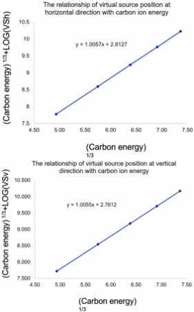
Figure 6. The distance of virtual source position of carbon ion beam in the horizontal and vertical direction can be integrated as a function of carbon ion energy in equation 3 and 4,respectively.
The distance of the virtual source position of the carbon ion beam in the horizontal and vertical direction can be integrated as a function of the carbon ion energy in equations 3 and 4, respectively in figure 6.
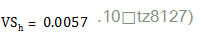 (3)
(3)
denotes the virtual source position in the horizontal direction, E means the virtual source position at this energy of carbon ion beam.
VSv denotes the virtual source position in the vertical direction, E means the virtual source position at this energy of the carbon ion beam.
The detailed process of the convergent arcCOS method for determining the virtual source position in the vertical direction of scanning-passive scatter beam in 330 MeV/u carbon ion therapy is listed in Table 3. The least squares error, 0.031153 (100 times of original value), happens at the assumed virtual source position, t, at 626 cm (with bold and underlined) in table 3. The virtual source position for the other carbon ion energies was derived following the processes described in tables 2, and 3 as well.
Table 4 shows the parameters a and b in the linear regression when y= 0, y denotes field size in y=a x +b, which means the virtual source position, x, happens at the back projection point when the field size becomes zero. The virtual source position derived by the cACOS method was also listed in Table 4 for comparison with the results derived by back projecting HWFM to zero methods.
The solution of x, in y=a x +b, the parameters a, and b, were listed in Table 4 which were generated by the same process of back projecting HWFM to zero methods to get the virtual source position for every energy.
The virtual source position for higher carbon ion energy has an obvious longer distance from the SAD since the more energy of the carbon ion beam, the less bending affected by the horizontal and vertical magnetism, therefore, virtual source positions from SAD are decreased from high to low carbon ion energy which was shown in table 4.
The relationship of virtual source position and carbon ion energy in horizontal and the vertical direction generated in equations 3 and 4, the comparison for calculation and measurements are agreed within 1%.
The MLC opening, as well as the fabrication of the compensator, were then corrected according to the measured virtual source position for every carbon ion energy in the horizontal and vertical directions. Furthermore, the MLC opening depends not only on the accuracy of the virtual source position but also depends on whether the MLC offset is carefully adjusted (17).
CONCLUSION
The essential contribution and usefulness of this study were to propose the convergent arcCOS method to minimize mistakes of any manual error caused by film measurements. The importance of precise virtual source position in the Monta Carlo simulation is indispensable. The calculation of radiation doses may not always be in agreement for MLC treatment fields at a carbon ion beam treatment planning system unless the virtual source position and MLC offset are well-calibrated. The method for investigating the virtual source position in a carbon ion beam in this study can be applied to the external electron beam and the proton beam.
ACKNOWLEDGMENT
The author appreciates Professor Ye Yan Cheng, and Professor Yan-Shan Zhang for their great contribution to this study.
Fundings: This work was supported by the Funding: Overseas high professional experts introduced projects of the Science and Technology Department, Gansu Province, China. (The clinical application of carbon ion beams in radiation oncology 22JR10KA029); Central government Guided Local fund projects of the Science and Technology Department of Gansu Province, China; Special project for popular science of Gansu Province, China (The most significant equipment in the field of radiotherapy- The fundamental principle, facility, and radiobiology in all aspects of carbon ion in radiation oncology 22JR10KA030).search for radiation oncology in carbon ion therapy 22ZY1QH001); Neoadjuvant chemotherapy combined with 3D brachytherapy in local late stage cervical cancer (WW2002079).
Declaration of conflicts of interests: The authors declare that they have no competing financial interests or personal relationships that could have appeared to influence the work reported in this paper.
Ethical approval statement: This paper is a topic of medical physics study. All data were gathered from our carbon ion beam, therefore, there is no need to get ethical approval from our institute.
Author contributions: J-M.W. contributed to the study concept and design. Y.Q, Y-S.Z. contributed to the acquisition of data. Y-S.Z. and Y-C.Y. contributed to the analysis and interpretation of data. T-F. L., J-M.W. contributed to the writing, reviewing, and approval of the final version of this work.
REFERENCES
1.Sawkey DL and Faddegon BA (2009) Determination of electron energy, spectral width, and beam divergence at the exit window for clinical megavoltage X-ray beams. Med. Phys, 36: 698–707.
2.Sham E, Seuntjens J, Devic S (2008) Influence of focal spot on characteristics of very small diameter radiosurgical beams. Med Phys, 35: 3317–3330.
3.Knöös T, Wieslander E, Cozzi L (2006) Comparison of dose calcula- tion algorithms for treatment planning in external photon beam therapy for clinical situation. Phys Med Biol, 51: 5785–5807.
4.Sterpin E, Tomsej M, De Smedt B (2007) Monte Carlo evaluation of the AAA treatment planning algorithm in a heterogeneous multi- layer phantom and IMRT clinical treatments for an Elekta SL25 linear accelerator Med Phys, 34: 1665–1677.
5.Bortfeld T and Schlegel W (2007) An analytical approximation of depth–dose distributions for theraputic proton beams. Phys Med Biol, 41: 1331–9.
6.Chetty IJ, Curran B, Cygler JE (2007) Report of the AAPM task group No. 105: Issues associated with clinical implementation of Monte Carlo-based photon and electron external beam treatment planning. Med Phys, 34: 4818–4853.
7.Kooy H, Rosenthal S, Engelsman M (2005) The prediction of output factors for spread-out proton Bragg peak fields in clinical practicePhys Med Biol, 50: 5847–56.
8.Kooy H, Schaefer M, Rosenthal S (2003) Monitor unit calculations for range-modulated spread-out Bragg peak fields Phys Med Biol, 48: 2797–8089.Petti PL (1992) Differential-pencil-beam dose calculation for charged particles. Med Phys, 19: 137–49.
10.Verhaegen F and Seuntjens J (2003) Monte Carlo modeling of external radiotherapy photon beams. Phys Med Biol, 48: R107– R164.
11.Russell KR, Isacsson U, Saxner M (2000) Implementation of pencil kernel and depth penetration algorithms for treatment planning of proton beams. Phys Med Biol, 45: 9–27.
12.Reynaert N, van der Marck SC, Schaart DR (2007) Monte Carlo treatment planning for photon and electron beams. Radiat Phys Chem, 76: 643–686.
13.Dreind -R ,Georg D, StockM ( 2014) Radiochromic film dosimetry: considerations on precision and accuracy for EBT2 and EBT3 type films. Med Phys, 24(2):153-163.
14.Kamomae T, MiyabeY, SawadaA (2011) Simulation for improve- ment of system sensitivity of radiochromic film dosimetry with different band-pass filters and scanner light intensities. Radiol Phys Technol, 4(2): 140-147.
15.García-Garduño OA, Lárraga-Gutiérrez JM, Rodríguez-Villafuerte M(2016) Effect of correction methods of radiochromic EBT2 films on the accuracy of IMRT QA. App RadiIsot, 107:121-126.
16.Barbara S (2008) Proton dose calculation based on in-air fluence measurements, Phys Med Biol 53:1545–1562.
17.Wu JM, Lee TF, Kuo CM (2012) A light field-based method to adjust rounded leaf end MLC position for split shape dose calculation correction in a radiation therapy treatment planning system, JAppl Clin Med Phys, 13(6): 3-18.