
The Determination of Virtual Source Position Using Poka-Yoke Concept to Minimize Mistakes for Scanni
The Determination of Virtual Source Position Using Poka-Yoke Concept to Minimize Mistakes for Scanning-Passive Scatter Beam in Carbon Ion Therapy
Yan-Cheng Yea, *, Yan-Shan Zhanga, **, Tsair-Fwu Leec, and Jia-Ming Wua,b,d, ***
a Heavy Ion Center of Wuwei Cancer Hospital; Gansu Wuwei Academy of Medical Sciences; Gansu Wuwei Tumor Hospital, Wuwei, Gansu, China
b Department of Medical Physics, Chengde Medical University, Chengde, Hebei, China
c Medical Physics and Informatics Laboratory of Electronic Engineering, National Kaohsiung University of Science and Technology, Kaohsiung 80778, Taiwan
d Department of Radiation Oncology, Yee Zen General Hospital, Taoyuan, Taiwan
*e-mail: zlyyyyc@163.com
**e-mail: 13830510999@163.com
***e-mail: jiaming.wu@chmsc.com
Received September 13, 2022; revised October 8, 2022; accepted December 9, 2022
Abstract−We developed a mistake-proofing technique (Poka-Yoke) capable of dealing with the virtual source position delivered by different carbon ion energies for scanning-passive scatter beam in carbon ion therapy. Despite a lot of methods that have been proposed for the determination of virtual source position for electron beam therapy in a linear accelerator and proton beams, none for heavy charged particles like carbon ions have been investigated. The method can also be used for electron and proton beams.
DOI: 10.1134/S0020441223030156
1.INTRODUCTION
The carbon ion beam, unlike an electron beam from a linear accelerator, does not emanate from a physical point source in the nozzle acceleration system [1–4]. A narrow energy-dependent spot size of the carbon ion beam, after passing through the horizontal and vertical scanning magnets in the vacuum window of the accelerator, primary collimator, beam monitor, spreading scatterer, ridge filter and ridge shifter, and range shifter, is scanned spreading into a broader two-dimensional field that appears to diverge from a point. This point is known as the virtual source position [5], which may be defined as an intersection point of the back projection along with the most probable directions of carbon ions motion at a fixed position, for example, on the plane at a nominal source-axis-distance. There are many investigations describing the method of determining the virtual source position by inverse square law correction for output at extended SSDs under all clinical conditions or by field size magnification on film with distance [6–9]. Despite a lot of methods that have been proposed for the determination of virtual source position for electron beam therapy in a linear accelerator and proton beam, none for heavy charged particles-like carbon ions have been investigated [10, 11]. The virtual source point needs to be measured by the back-projection of the 50% width of the beam profiles acquired at different distances upstream or downstream of the source [12]. In our facility, a certain beam field size without the collimation of multi-leaves collimator (MLC), the largest field size was used for measurements in this study. The measurement of virtual source position for carbon ion beams was unusual than in electron beam therapy, the measurement of virtual source position cannot apply by inverse square law correction from chamber output at extended SSDs since no inverse square response is available for the chamber along the carbon beam’s percent depth dose curve on the plateau at different distances.
The Institute of Modern Physics (IMP) was founded in 1957 in Lanzhou, China. The National Laboratory of Heavy Ion Accelerator, Lanzhou (NLHIAL) was established at IMP in 1991 to take the advantage of full usage of the research facilities at IMP [8]. WuWei Heavy Ion Center, Wuwei Cancer Hospital, GanSu, China (WHICH) consists main synchrotron ring to accelerate sufficient particle energy and flux for four treatment rooms used-room 2, equipped with a horizontal, and a vertical nozzle aimed at one isocenter with scanning-passive scatter beam, was adopted for the virtual source position study. The importance of the virtual source position not only fits the need of correcting the opening of the multi-leaf collimator in field sizes but also supports the fabrication of compensators for carbon ion therapy for the patient-specific dosimetric calculation in the treatment planning system.
The virtual source position for carbon ion beams of energies 120, 190, 260, 330, and 400 MeV/u in the WHICH have been measured. It is realized that the virtual source position’s issue in the electron beam is highly energy-dependent, therefore, if the issue is also highly energy and field size-dependent for the carbon ion beam then the virtual source position needs to be measured carefully for each nozzle.
The virtual source position was intended to be determined with the conventional back projecting zero method and was double checked additionally by the Poka-Yoke technique to minimize mistakes by exposing a certain field on CMOS sensor and films in the air with an interval of some distance upstream and downstream from nominal source-axis distances for beam profiles analysis.
2.MATERIALS AND METHODS
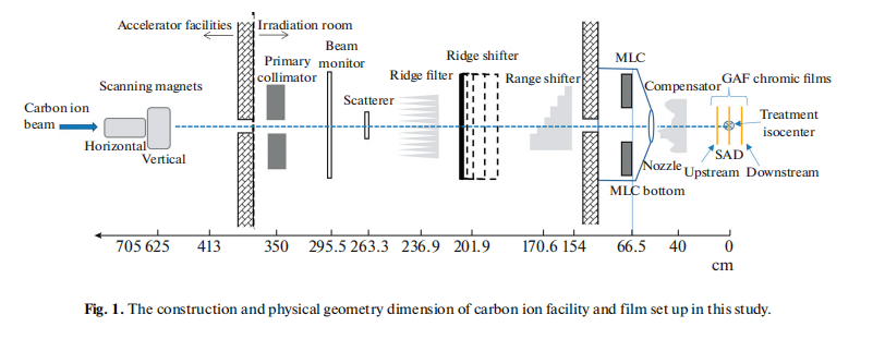
A horizontal beam equipped in room 2 was adopted for the effective source position measurement in this study; the construction and physical geometry dimension of our carbon ion facility is shown in Fig. 1. The carbon ion beam passes a horizontal magnet scanning at x direction first and then through to a vertical magnet scanning at y direction to create the scanned x–y field size for clinical use. The ridge filter, ridge shifter, and range shifter, as well as compensator, were removed with only the primary collimator opened during the measurement in this study.
Carbon ions with initial energies ranging from 120 to 400 MeV/u in increments of 70 MeV/u and field sizes set by the horizontal–vertical magnets at a machine opening field size were used for the measurements of the virtual source position at our institute in this study. The distance between the 50% of the central axis value from the profiles was measured and denoted as the full width half maximum (FWHM). The FWHM was measured and plotted as a reciprocal profile using the measurement of machine opening field with different distances measured upstream or downstream within 50 cm from the point of SAD.
The linear relationship of the beam’s FWHM in air appears to diverge geometrically from a point source where the beam width is zero when projecting these lines back to the central axis. Conversely, the ratio of each different field size and its relative virtual source position converges to a unique value when an exact assumed virtual source position is given. The virtual source position determined using the triangular geometry ratio method can be used to double-check the back projecting zero method to avoid any manual measurement mistakes in scanning-passive scatter carbon ion beam.
3.EXPERIMENT
3.1. Experiment Setup in the Treatment Room
In this study, a homemade large-format CMOS sensor by IMP was conducted as an FWHM detector for measurement in carbon scanning-passive scatter beam study. The large-format CMOS sensor was set up on the treatment couch in the air with the detector surface facing perpendicularly to the carbon ion beam at the point of nominal source-axis-distance (SAD) as well as upstream at 20, 40, and 50 cm and downstream at 10.4 cm from the point of SAD in Fig. 1.The FWHMs were mainly measured by the large-format CMOS sensor and Gaf Chromic EBT3 films were used to double checking the CMOS profiles. Gaf Chromic EBT3 films were embedded in a self-designed rectangular plastic frame to tight the films and set up on the treatment couch in the air with the film perpendicular to the carbon ion beam at the point of nominal source-axis-distance (SAD) as well as upstream and downstream 20 cm from the point of SAD in Fig. 1. Both the measurement of CMOS and the Gaf Chromic EBT3 film in horizontal carbon ion beam with 5 energies at a maximum field size of 231.875 × 234.827 mm for the measurements for virtual source position were carried out in this study.
3.2. The FWHM Measurement with the CMOS Sensor and the GAF EBT 3 Films
The large-format CMOS sensor was placed on the treatment couch with the detector frontal face to the horizontal nozzle. All five energy of carbon ion beams were evaluated during this investigation.
The large-format CMOS signals were in pixels and the Gaf Chromic EBT3 films (Ashland Specialty Ingredients GP, NJ USA; Lot #04022002, Exp. Date: April 2023) was adopted for the dose profile measurement in determining the virtual source position for this study. The dose profile of exposed film was processed following international protocols [13]. Films were conducted with a pre-exposure technique to reduce the uncertainty in deriving the calibration curve [14]. A priming dose of 2 Gy was given with the carbon ion energy of 330 MeV/u for each film to homogenize the film density. The films then measured the dose homogeneity using a densitometer. The graded doses from 10 to 200 cGy were given to the GAF chromic film to obtain the Hurter−Driffield calibration curve (H–D-curve).
3.3. Derivation of Horizontal and Vertical Magnets Driven Dose Profile to Get the FWHM
The FWHM of dose profiles measured by the large-format CMOS detectors were mainly adopted for the virtual source position study. All exposed films of the desired field size were then scanned with an Epson Expression 11000XL scanner in the 72 dpi mode (0.353 mm per dot interval), and the data were saved as tagged image file format (TIFF) and analyzed by the filmQA Pro v7(Ashland, USA) imaging procession software. A red filter was placed on top of the GAF films for raising the resolution of the dose-OD curves before scanning to increase the slope of the H−D-curve [15].
3.4. Determine the Horizontal Beam Line’s Virtual Source Position by Back Projecting the Width of Different FWHM Downstream or Upstream from Various Source-Film-Distance
Firstly, plot the FWHM versus nominal distance curves for every point of SAD, upstream, downstream based on the film setup geometry in Fig. 1. Secondly, derive the parameters of a and b by linear regression (y = ax + b, where y denotes FWHM, x is the virtual source position from the point of nominal SAD shown in Fig. 1) from the curves created by the FWHM versus the point of nominal distance. Thirdly, let y = 0 then the virtual source position can be derived from b divided by a, negative value denotes the virtual source position is upstream from SAD toward carbon ion source virtual point.
3.5. A Geometric Convergent Method for Double Checking the Back Projecting Zero Methods to Avoid any FWHM Manual Measurement Mistakes
A technique called the Poka-Yoke concept capable of dealing with the virtual source position with a triangular geometric convergent method was adopted to avoid any FWHM manual measurement mistakes in scanning-passive scatter carbon ion beam. The ratio of the half measured FWHM with its relative assumed virtual source position will become a unique value with all ratio’s deviation converging to a minimum value from downstream to upstream, here, the so-called half measured FWHM can be selected the right or the left side’s half FWHM, usually the left side half FWHM might not equal to the right-side half FWHM.
4.RESULTS
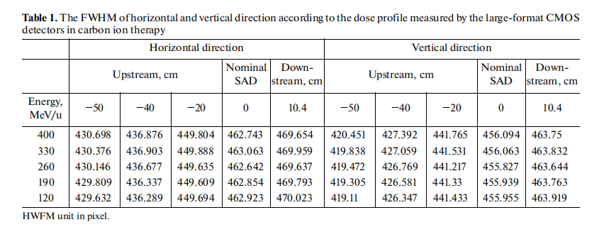
Table 1 shows the FWHM in horizontal (x direction) and vertical (y direction) dose profiles measured by the large-format CMOS detectors in carbon ion therapy. Film dose profile’s FWHM for all carbon ion energies had been compared with CMOS, and the results were within 1.5%.
Figures 2a–2e display the parameters a and b of the linear regression y = ax + b, and the virtual source position can then be derived from b divided by a. The virtual source position is upstream negatively from SAD toward the carbon ion source point for each carbon ion energy from 120 to 400 MeV/u in the horizontal and vertical directions.
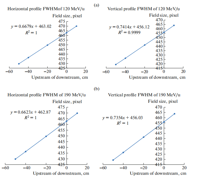
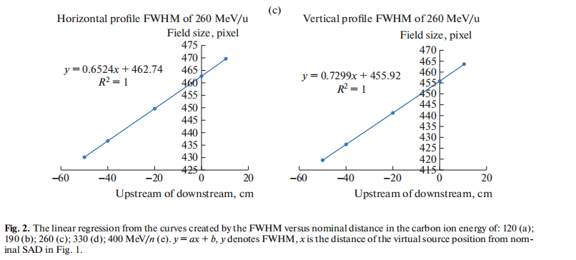
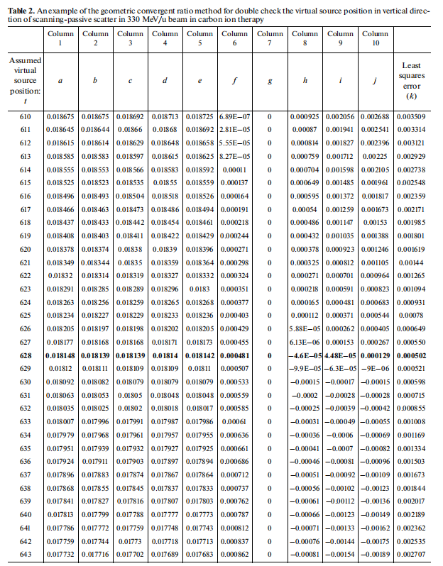
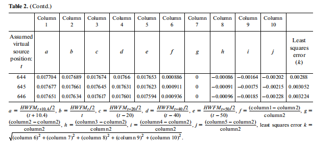
Table 2 is an example of the geometric convergent ratio method for double checking the virtual source position in the vertical direction of scanning-passive scatter in 330 MeV/u beams in carbon ion therapy. The ratio of the half measured FWHM with its reflective assumed virtual source position will become a unique value with all ratio’s deviation converging to a minimum value of a distance of 628 cm (bold and underlined in Table 2) from downstream to upstream.
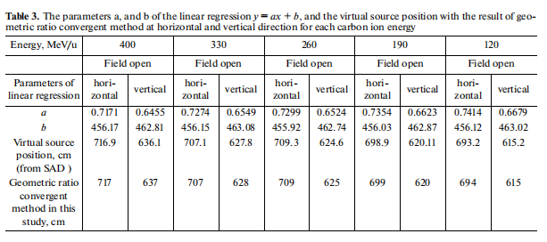
Table 3 lists the parameters a and b of the linear regression y = ax + b, and the virtual source position with the result of the geometric ratio convergent method at horizontal and vertical direction for each carbon ion energy.
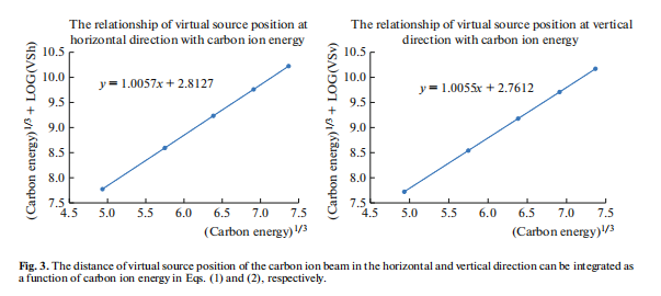
The distance of the virtual source position of the carbon ion beam in the horizontal and vertical directions can be integrated as a function of carbon ion energy (Fig. 3):

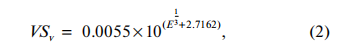
where VSh, denotes the virtual source position in the respectively horizontal and vertical direction, E means the energy of the carbon ion beam relative to its virtual source position.
- DISCUSSION
Unlike the X-ray generated from a linear accelerator, a carbon ion beam does not emanate from a physical source in the accelerator head. The point called the virtual source of the electron beam is a pencil electron beam passing through the bending magnets, scattering foils, monitor chambers in the head of the accelerator, is spread into a sufficient clinical available field size that appears to diverge from a point. Measurements of the virtual source position of the electron beam can use the inverse square law method by the reading of the ion chamber to correct the dose output as a function of the air gap between the electron applicator end and the measurement position, but the inverse square law method is no longer used for carbon ion beam since the percent depth dose of the carbon ion beam is just the reverse of electron beam’s percent depth dose which is well known of plateau-Bragg peak curve. There are few studies regarding the measurement of virtual source position on heavy charged particles. A cross-profile measurement of the proton fluency in the air at different positions from the isocenter was studied for determining the proton virtual source position [16].
Although several methods have been suggested for the determination of virtual source position in electron, the virtual point source of a carbon ion beam has never been investigated and can be treated as the intersection point of the back projections along with the most probable directions of motion like electron at the film measured. The virtual source position may also be defined as a zero-field size intersection point of the FWHM back projections along with the most probable directions of the carbon ion beam where the film was measured. The field provided by the carbon ion beam in our facility in room 2 is a scanning-passive scatter type in Fig. 1 which is rather than a broad beam like the electron, thus, the virtual source point needs to be investigated separately in the horizontal (x direction) and vertical (y direction) of the beam profiles driven by horizontal and vertical magnets using the back projections of the 50% width to zero at different measurement distances.
The technique developed for carbon ion beam delivery in our facility for room 2 is scanning-passive scattering. In this approach, not like the beam that is spread using scatter foils, the delivery of scanning-passive scattering beams of our carbon ion beams was formed by thousands of narrow and quasi-monoenergetic carbon pencil-like beams magnetically by horizontal first and then go through vertical magnets to pass a scatterer for covering a full field where the Bragg peak reach following the carbon ion energy.
The FWHM of the profile in the horizontal direction and in the vertical for each energy were shown in Table 1. The unit of FWHM in the horizontal and vertical direction in dose profile measured by the large-format CMOS detectors was in pixel, a pixel equals 0.5 mm, therefore, the field size of carbon ion energy 330 MeV/u at the nominal SAD was 231.53 by 231.92 mm in the horizontal and vertical directions shown in Table 1, respectively.
Table 2 shows an example of the geometric convergent ratio method for double checking the virtual source position derived by the back projecting zero methods in the vertical direction of scanning-passive scatter in 330 MeV/u beams in carbon ion therapy. Column 1 to column 5 shows the ratio of half HWFM with its reflective assumed virtual source position with different upstream or downstream shifts, column 1 to column 5 calculates the deviation of each ratio compared with the ratio of virtual source position at nominal SAD (the calculation can be compared to any measured point, like at t + 10.4, or t + any shift distance toward upstream). The least squares error will converge to its minimum value when the virtual source position is reached, in this example, the virtual source position at the vertical direction of scanning-passive scatter of 330 MeV/u is located at 628 cm with bold and underlined in Table 2. With this simple geometric ratio Poka-Yoke method for double checking the errors caused by manual measurements of film or detector’s FWHM, the user can apply it to all virtual source position measurement for any carbon ion energy in the horizontal and vertical directions.
The very left column of the following Table 2 indicates the assumed virtual source position, this value was adopted to calculate the ratio of (HWFMt + 10.4/2)/(t + 10.4), this ratio also stands for the converged angle, α, which can be derived by the arcTAN. Then for each column denoted as HWFMt+10.4 represents the calculation ratio at the distance downstream 10.4 cm from the point of nominal SAD (source-axis distance); HWFMt (HWFMt+0) represents the calculation for HWFM at the distance from the point of nominal SAD (source-axis distance); HWFMt−20, HWFMt−40, HWFMt−50 represents the calculation for HWFM at the distance upstream 20, 40, and 50 m from the point of nominal SAD (source-axis distance), respectively. The column “(column 1–column 2)/column 2” means the deviation of the calculation results between HWFMt+10.4 with HWFMt+0 when the same assumed virtual source position was given, et al. The exact virtual source position is found when the deviation converges to a smallest value as shown the position of 628 cm while the exact virtual source position was found at position of 628 cm with the smallest least square errors of 0.00502413 in Table 2 in the following table, and is shown in the revised manuscript as well.
The solution of x, in y = ax + b, the parameters a, and b, were listed in Table 3 which were generated from Figs. 2a–2e to get the virtual source position for every energy. The parameters a and b shown in Table 3 were derived from the linear regression from Figs. 2a–2e. When y = 0, y denotes field size in y = ax + b, which means the virtual source position, x, happens at the back projection point when the field size becomes zero. The virtual source position for higher carbon ion energy has an obvious longer distance from the SAD since the more energy of the carbon ion beam, the less spreading affected by the horizontal and vertical magnetism, therefore, virtual source positions from SAD are decreased from high to low carbon ion energy which was shown in Table 3. The virtual source position derived from the back projecting zero methods was compared with the geometric ratio Poka-Yoke method in Table 3.
The distance of the virtual source position of a carbon ion beam in the horizontal and vertical direction can be integrated as a function of carbon ion energy in Eqs. (1) and (2) in Fig. 3, respectively. The virtual source position in the horizontal and vertical direction can be presented by how: It’s ok for the correction of the presentations, thanks!
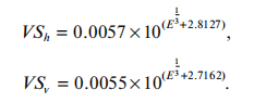
The relationship between virtual source position and carbon ion energy in horizontal and vertical directions is described by Eqs. (1) and (2), with the calculated and measured results agreeing within 1%.
The MLC opening, as well as the fabrication of compensators, were subsequently corrected based on the measured virtual source position for each carbon ion energy in both horizontal and vertical directions. Furthermore, the MLC opening depends not only on the accuracy of the virtual source position but also on whether the MLC offset is carefully adjusted [17].
CONCLUSIONS
The study regarding virtual source position in carbon ion therapy is novel, and we have developed a technique capable of determining the virtual source position using a geometric convergent method to minimize errors in scanning-passive scatter carbon ion beam at our facility. The method for investigating the virtual source position in carbon ion beams presented in this study can also be applied to external electron beams and proton beams. The precise determination of the virtual source position is indispensable for Monte Carlo simulations.
Dose calculations may not consistently agree with MLC-defined treatment fields in carbon ion treatment planning systems unless the virtual source position and MLC offset are accurately calibrated. The current method does not account for effects from MLC thickness or compensator scattering. However, extending this method to incorporate these factors, as well as applications in pencil beam scanning, is feasible and currently under development.
ACKNOWLEDGMENTS
The authors appreciate Professor Yan-Shan Zhang and Professor Tsair-Fwu Lee for their significant contributions to this study. Professor Yan-Shan Zhang is considered a co-first author (with equal contribution), and Professor Tsair-Fwu Lee is a co-corresponding author (with equal responsibility for correspondence).
FUNDING
This work was supported by the funding: Central government Guided Local fund projects of Science and Technology Department of Gansu Province, China. (The Precise therapy platform of clinical and research for radiation oncology in carbon ion therapy 22ZY1QH001.) This work was supported by the Funding: Overseas high professional experts introduced projects of the Science and Technology Department, Gansu Province, China. (The clinical application of carbon ion beams in radiation oncology 22JR10- KA029).This work was supported by the Funding: Special project for popular science of Gansu Province, China (The most significant equipment in the field of radiotherapy- The fundamental principle, facility, and radiobiology in all aspects of carbon ion in radiation oncology 22JR10- KA030).
COMPETING INTERESTS
There are no actual or potential competing interests in this study. This manuscript has not been published nor concurrently submitted for publication elsewhere.
Preliminary Review: Zhang Jie Final Review: Zhang Lihong