
Determination of virtual source position using back projecting zero and convergent arcTAN method for
Determination of virtual source position using back projecting zero and convergent arcTAN method for scanning-passive scatter beam in carbon ion therapy
Wan-Bin Menga,b, Qiang Lia,∗, Yan-Cheng Yec and Jia-Ming Wuc,d,e,∗
a Institute of Modern Physics, Chinese Academy of Sciences, Lanzhou, China
b University of Chinese Academy of Sciences, Beijing, China
c Heavy Ion Center of Wuwei Cancer Hospital; Gansu Wuwei Academy of Medical Sciences, Gansu
Wuwei Tumor Hospital, Wuwei City, Gansu Province, China
d Department of Medical Physics, Chengde Medical University, Chengde City, Hebei Province, China
e Department of Radiation Oncology, Yee Zen General Hospital, Tao Yuan City, Taiwan
Abstract
OBJECTIVE: This study aims to develop and test a new technique using the convergent arcTAN (cATAN) method to handle the virtual source position delivered by different carbon ion energies from the scanning-passive scatter beam pattern.
MATERIALS AND METHODS: A homemade large-format CMOS sensor and Gaf Chromic EBT3 films were used to measure the virtual source position. The Gaf films were embedded in a self-designed rectangular plastic frame to secure them and placed on a treatment couch for irradiation in air, with the film perpendicular to the carbon ion beam at the nominal source-axis-distance (SAD), as well as upstream and downstream from the SAD. A horizontal carbon ion beam with five energies at a machine opening field size was employed. The virtual source position was determined using the convergent arcTAN (cATAN) method and compared with linear regression by back-projecting FWHM to zero at various source-film distances.
RESULTS: A film FWHM measurement error of 0.5 mm led to a 0.001% deviation of θ (cATAN) at every assumed textend. The overall uncertainty for the reproducibility of the calculated virtual source position by the assumed textend in the vertical and horizontal directions amounted to 0.1%. The errors of the calculated virtual source position by the assumed textend with back-projecting FWHM to zero methods were within 1.1 ± 0.001, p = 0.033.
CONCLUSION: We developed a new technique using the convergent arcTAN method to determine the virtual source position, which helps avoid manual measurement errors in scanning-passive scatter carbon ion beams. Readers are encouraged to apply the proposed cATAN method to investigate virtual source positions in Linac-based external electron beams and proton beams.
Keywords: Carbon ion beams, virtual source position, scanning-passive scatter beam
1.Introduction
The carbon ion beam, unlike an electron beam from a linear accelerator, does not emanate from a physical point source in the nozzle acceleration system [1–4]. A narrow energy-dependent spot size of the carbon ion beam, after passing through the horizontal and vertical scanning magnets in the vacuum window of the accelerator, primary collimator, beam monitor, spreading scatterer, ridge filter and ridge shifter, and range shifter, is scanned spreading into a broader two-dimensional field that appears to diverge from a point. This point is known as the virtual source position [5], which may be defined as an intersection point of the back projection along with the most probable directions of carbon ions motion at a fixed position, for example, on the plane at a nominal source-axis-distance.
There are many investigations describing the method of determining the virtual source position by inverse square law correction for output at extended SSDs under all clinical conditions or by field size magnification on film with distance [6–9]. Despite a lot of methods that have been proposed for the determination of virtual source position for electron beam therapy in a linear accelerator and proton beam, none for heavy charged particles-like carbon ions have been investigated [10–12]. Usually, the virtual source point needs to be measured by the back-projection of the 50% width of the beam profiles acquired at different distances upstream or downstream of the source in external electron therapy [13]. In our facility, a certain beam field size without the collimation of multi-leaves collimator (MLC), the largest field size was used for measurements in this study. The measurement of virtual source position for carbon ion beams was unusual than in electron beam therapy, the measurement of virtual source position cannot apply by inverse square law correction from chamber output at extended SSDs since no inverse square response is available for the chamber along the carbon beam’s percent depth dose curve on the plateau at different distances.
The Institute of Modern Physics (IMP) was founded in 1957 in Lanzhou, China. The National Laboratory of Heavy Ion Accelerator, Lanzhou (NLHIAL) was established at IMP in 1991 to take the advantage of full usage of the research facilities at IMP [8]. WuWei Heavy Ion Center, Wuwei Cancer Hospital, GanSu, China (WHICH) consists main synchrotron ring to accelerate sufficient particle energy and flux for four treatment rooms used- room 2, equipped with a horizontal, and a vertical nozzle aimed at one isocenter with scanning-passive scatter beam, was adopted for the virtual source position study. The importance of the virtual source position not only fits the need of correcting the opening of the multi-leaf collimator in field sizes but also supports the fabrication of compensators for carbon ion therapy for the patient-specific dosimetric calculation in the treatment planning system.
The virtual source position for carbon ion beams of energies 120, 190, 260, 330 MeV/u, and 400 MeV/u in the WHICH have been measured. It is realized that the virtual source position’s issue in the electron beam is highly energy-dependent, therefore, if the issue is also highly energy and field size-dependent for the carbon ion beam then the virtual source position needs to be measured carefully for each nozzle.
The dosimetric characteristics of step-by-step Linear Energy Transfer (LET) inside the human body of carbon ion passive-scatter beams generated by IMP cyclotron-synchrotron accelerators depending on the horizontal and vertical scanning magnets in the vacuum window of the accelerator, primary collimator, beam monitor, spreading scatterer, ridge filter, and ridge shifter, and range shifter. For the majority of clinical situations, not only the LET for dose calculation but also the field size opened by Multi-Leaf Collimator of passive-scatter design was influenced significantly by the virtual source position in carbon ion beams. This study is to remedy a defect of no investigation for the virtual source position of carbon ions beam.
The essential contribution and usefulness of this study were to propose the convergent arcTAN method to minimize mistakes of any manual error caused by film measurements. The importance of precise virtual source position in the Monta Carlo simulation is indispensable. The calculation of radiation doses may not always agree for MLC treatment fields at a carbon ion beam treatment planning system unless the virtual source position and MLC offset are well-calibrated. The method for investigating the virtual source position in a carbon ion beam in this study can be applied to the external electron beam and the proton beam.
2.Materials and methods
The virtual source position was intended to be determined with the conventional back projecting zero methods and was double-checked additionally by the convergent arcTAN method to minimize mistakes caused by manual measurement by exposing a certain field on CMOS sensor and films in the air with an interval of some distance upstream and downstream from nominal source-axis distances for beam profiles analysis.
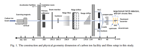
A horizontal beam equipped in room 2 was adopted for the effective source position measurement in this study, the construction and physical geometry dimension of our carbon ion facility is shown in Fig. 1. The carbon ion beam passes a horizontal magnet scanning at x direction beam first and then through to a vertical magnet scanning at y direction beam to create the scanned x-y field size for clinical use. The ridge filter, ridge shifter, and range shifter, as well as compensator, were removed with only the primary collimator opened during the measurement in this study.
The carbon ion with an initial energy of 120 MeV/u to 400 MeV/u in an increasing interval of 70 MeV/u and field sizes set by the horizontal-vertical magnets at a machine opening field size was carried out for the measurements of the virtual source position at our institute in this study. The distance between the 50% of the central axis value from the profiles was measured and denoted as the full width half maximum (FWHM). The FWHM was measured and plotted as a reciprocal profile using the measurement of the machine opening field with different distances measured upstream or downstream within 50 cm from the SAD.
The linear relationship of the beam’s FWHM in the air appears to diverge geometrically from a point source where the beam width is 0 when projecting these lines back to the central axis. On the contrary, the angle of arcTAN at each different field size and its relative virtual source position converges to one unique value when an exact assumed virtual source position is given. The virtual source position using the convergent arcTAN method can be used to double check with the back projecting zero methods to avoid any manual measurement mistakes in the scanning-passive scatter carbon ion beam. We then proposed the convergent arcTAN (cATAN) method for determining the virtual source position and compared it with the conventional FWHM back projecting to zero methods with a distance upstream from the various source-film-distance.
2.1. A. Experiment setup in the treatment room
In this study, an IMP home-made large-format OmniVision (Shanghai, China) model OV9712 and Aptina (ON Semiconductor, Phoenix, AZ, USA) model AR0130 COTS CMOS active pixel sensors (APSs) were used as an FWHM detector for measurement in carbon scanning-passive scatter beam measurement. The CMOS COTS digital sensors are energy independent and can be used for particle counting to a radiation dosage of 51.24 Gy after good calibration of linearity and reproducibility to reduce background noise. The CMOS COTS sensors. The large-format CMOS sensor was set up on the treatment couch in the air with the detector perpendicular face to the carbon ion beam at the nominal source-axis-distance (SAD) as well as upstream at 20 cm, 40 cm, and 50 cm and downstream at 10.4 cm from the SAD in Fig. 1.
Gaf Chromic EBT3 films were used to double checking with CMOS profiles. Gaf Chromic EBT3 films were embedded in a self-designed rectangular plastic frame to tight the films and set up on the treatment couch in the air with the film perpendicular to the carbon ion beam at the nominal source-axis-distance (SAD) as well as upstream and downstream 20 cm from the SAD in Fig. 1. Both the measurement of CMOS and the Gaf Chromic EBT3 film in horizontal carbon ion beam with 5 energies at a maximum field size of 231.875 mm × 234.827 mm for the measurements of virtual source position were carried out in this study.
2.2. B. The FWHM measurement with the CMOS sensor and the GAF EBT 3film
The large-format CMOS sensor was placed on the treatment couch with the detector frontal face to the horizontal nozzle, corresponding to the beam entering from the top (front face) of the detector. All five energy of carbon ion beams could be evaluated during this investigation.
The large-format CMOS signals were in pixels and the Gaf Chromic EBT3 films (Ashland Specialty Ingredients GP, NJ USA; Lot # 04022002, Exp. Date: April 2023) was adopted for the dose profile measurement in determining the virtual source position for this study. The dose profile of exposed film was processed following international protocols [14]. Films were conducted with a pre-exposure technique to reduce the uncertainty in deriving the calibration curve [15]. A priming dose of 2 Gy was given with the carbon ion energy of 330 MeV/u for each film to homogenize the film density. The films then measured the dose homogeneity using a densitometer. The graded doses of 10 to 200 cGy in an interval of 10 cGy were given to the GAF chromic film to obtain the Hurter-Driffield calibration curve (H-D curve).
2.3. C. Derivation of horizontal and vertical magnets driven dose profile to get the FWHM
The FWHM of dose profiles measured by the large-format CMOS detectors were mainly adopted for the virtual source position study. All exposed films of the desired field size were then scanned with an Epson Expression 11000XL scanner in the 72dpi mode (0.353 mm per dot interval), and the data were saved as tagged image file format (TIFF) and analyzed by the filmQA Pro v7(Ashland, USA) imaging procession software. A red filter was placed on top of the GAF films for raising the resolution of the dose-OD curves before scanning to increase the slope of the H-D curve [16].
2.4. D. Determine the horizontal nozzle virtual source position by the converged arcTAN (cATAN) method at the various source-film-distance
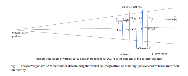
The method of the convergent arcTAN (cATAN) was displayed in Fig. 2, t denotes the assumed length of virtual source position from nominal SAD, and FS is the field size at the detector position. This method was based on the angle of arcTAN, α will converge to a unique value in arcTAN calculation when an assumed virtual source position, t is given to all different upstream of downstream distances. The virtual source position was then calculated by converged arc TAN method with the assumed virtual source position, t, in t at nominal SAD, tupstream with upstream distances at 20 cm, 40 cm, 50 cm, and tdownstream with downstream distances at 10.4 cm.
2.5. E. Determine the horizontal nozzle virtual source position by back projecting the distance between FWHM at the various source-film-distance
Firstly, plot the FWHM versus nominal distance curves for every SAD, upstream, downstream based on the film setup geometry in Fig. 1 Secondly, derive the linear regression (y = a x + b, y denotes FWHM, x is the virtual source distance in the film set up geometry in Fig. 1) from the curves created by the FWHM versus nominal distance given by the assumed virtual source position of t. The virtual source position, x, can be derived by letting y be zero, which means the virtual source position is derived from a distance upstream from the various source-film-distance with the back projecting method when the FWHM is zero.
The results of the virtual source position calculated by the convergent arcTAN (cATAN) method were compared with the results of the conventional FWHM back projecting to zero methods.
3 Results
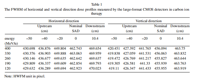
Table 1 is the FWHM of horizontal and vertical direction dose profiles measured by the large-format CMOS detectors in carbon ion therapy.
The film’s dose profile FWHM for all carbon ion energies had been spot compared with CMOS, and the results were within 1.5%. Detail film profile analysis to generate FWHM please refer to Appendix A which was demonstrated for 330 MeV/u and certain field sizes.
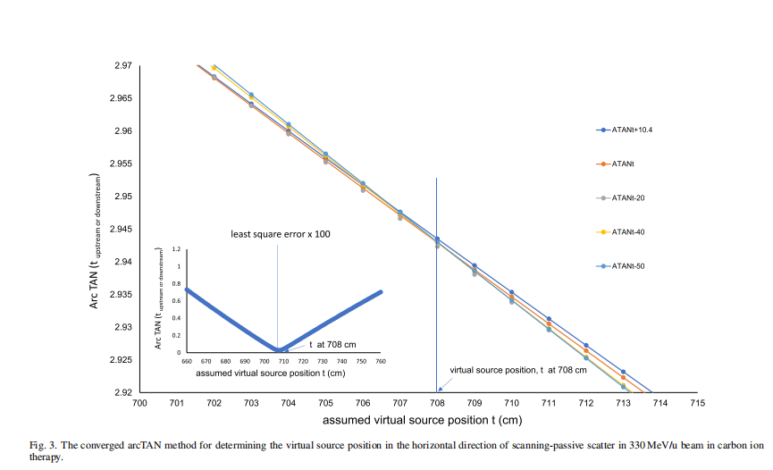
The convergent arcTAN method for determining the virtual source position in the horizontal direction of scanning-passive scatter for 330 MeV/u beam energy in carbon ion therapy was demonstrated in Fig. 3.
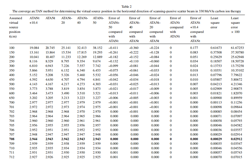
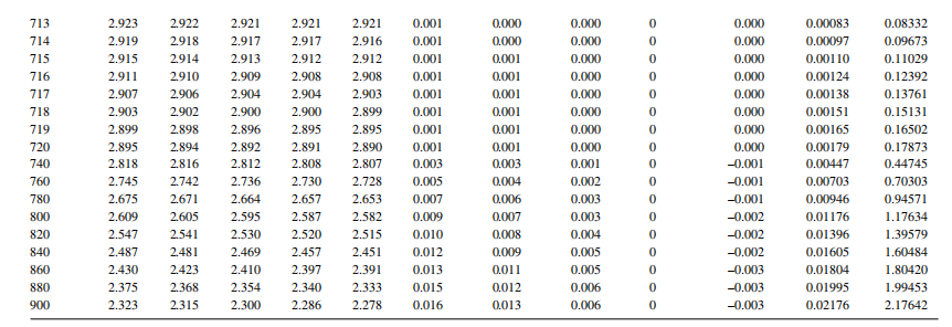
The convergent arcTAN method for determining the virtual source position in the horizontal direction of scanning-passive scatter beam in 330 MeV/u carbon ion therapy is listed in Table 2.
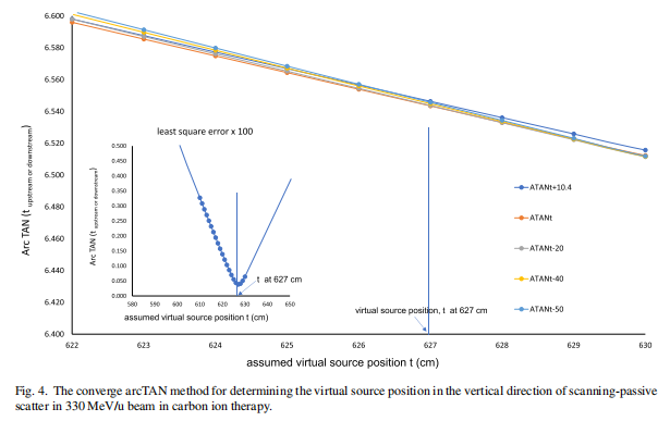
Again, a similar procedure for the converged arcTAN method for determining the virtual source position in the vertical direction of scanning-passive scatter for 330 MeV/u beam energy in carbon ion therapy was demonstrated in Fig. 4.
The converge arcTAN method for determining the virtual source position in the vertical direction of scanning-passive scatter in 330 MeV/u beam in carbon ion therapy is listed in Table 3.
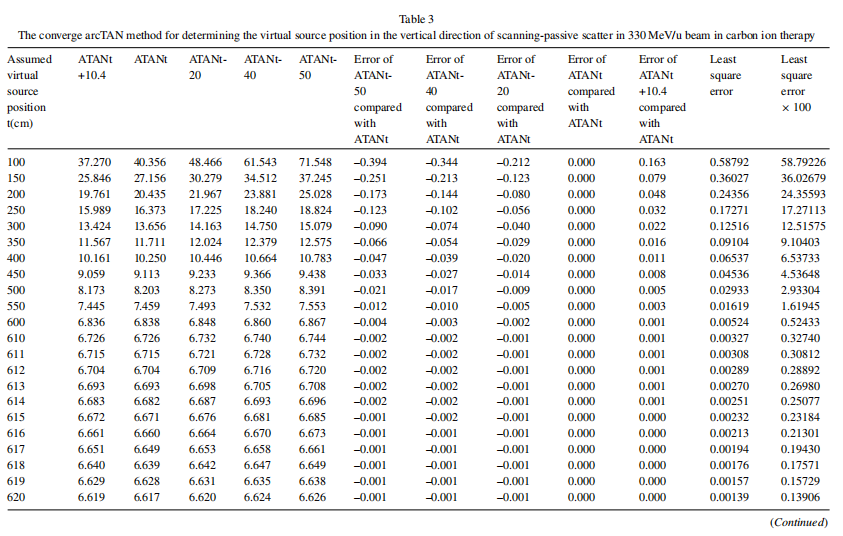
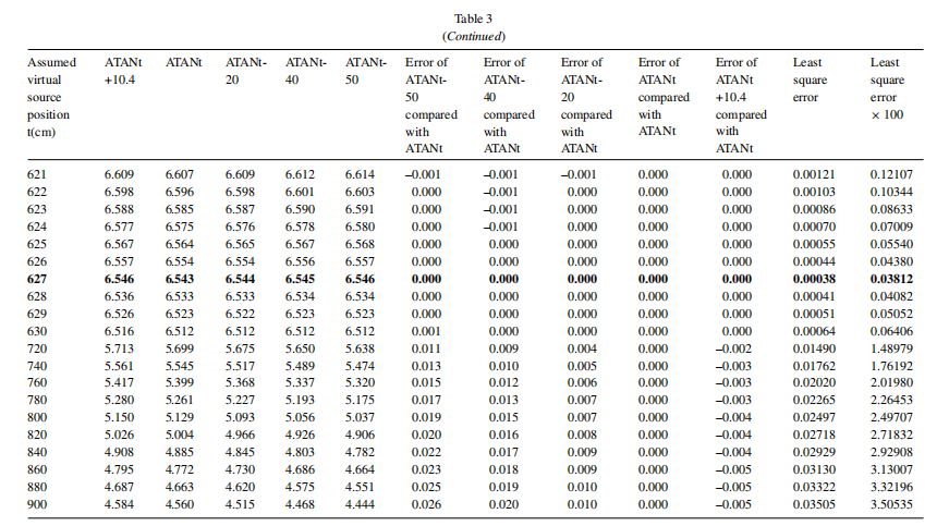
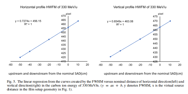
Figure 5 demonstrates the determination of parameters a, and b in the horizontal and vertical direction at the carbon ion energy of 330 MeV/u with linear regression of y = a x +b, where y denotes FWHM, x is the virtual source distance. The virtual source position for every carbon ion energy from 120 MeV/u to 400 MeV/u in the horizontal and vertical directions can be derived with the same method of back projecting FWHM to be zero.
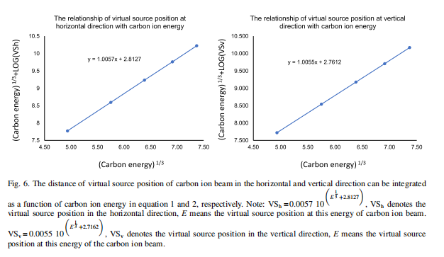
The parameters a, and b of the linear regression y = a x +b, and the virtual source position derived by back projecting FWHM zero method and cATAN method for each carbon ion energy at horizontal and vertical direction is listed in Table 4.The distance of the virtual source position of the carbon ion beam in the horizontal and vertical direction can be integrated as a function of carbon ion energy in equations 1 and 2, respectively in Fig. 6.
4.Discussion
Unlike the x-ray generated from a linear accelerator, a carbon ion beam does not emanate from a physical source in the accelerator head. The point called the virtual source of the electron beam is a pencil electron beam passing through the bending magnets, scattering foils, monitor chambers in the head of the accelerator, and is spread into a sufficient clinical available field size that appears to diverge from a point. Measurements of the virtual source position of the electron beam can use the inverse square law method by the reading of the ion chamber to correct the dose output as a function of the air gap between the electron applicator end and the measurement position, but the inverse square law method is no longer used for carbon ion beam since the percent depth dose of the carbon ion beam is just the reverse of electron beam’s percent depth dose which is well known of plateau-Bragg peak curve. There are few studies regarding the measurement of virtual source position on heavy charged particles. A cross-profile measurement of the proton fluency in the air at different positions from the isocenter was studied for determining the proton virtual source position [17].
Although several methods have been suggested for the determination of virtual source position in electron, the virtual point source of a carbon ion beam has never been investigated and can be treated as the intersection point of the back projections along with the most probable directions of motion like electron at the film measured. The virtual source position may also be defined as a zero-field size intersection point of the FWHM back projections along with the most probable directions of the carbon ion beam where the film was measured. The field provided by our facility in room 2 is a scanning-passive scatter type in Fig. 1 which is rather than a broad beam like the electron, thus, the virtual source point needs to be investigated separately in the horizontal (x direction) and vertical (y direction) of the beam profiles driven by horizontal and vertical magnets using the back projections of the 50% width to zero at different measurement distances.
The technique developed for carbon ion beam delivery in our facility for room 2 is scanning-passive scattering. In this approach, not like the beam that is spread using scatter foils, the delivery of scanning-passive scattering beams of our carbon ion beams was formed by thousands of narrow and quasi-monoenergetic carbon pencil-like beams magnetically by horizontal first and then go through vertical magnets to pass a scatterer for covering a full field where the Bragg peak reach following the carbon ion energy.
The FWHM of the profile in the horizontal direction and in the vertical for each energy were shown in Table 1. The unit of FWHM in the horizontal and vertical direction in dose profile measured by the large-format CMOS detectors was in pixel, a pixel equals 0.5 mm, therefore, the field size of carbon ion energy 330 MeV/u at the nominal SAD was 231.53 mm by 231.92 mm in the horizontal and vertical directions shown in Table 1, respectively.
The curves of different arcTAN values calculated by the assumed virtual source position in the horizontal direction, t, in t at nominal SAD, tupstream with upstream distances at 20cm, 40 cm, 50 cm, and tdownstream with downstream distances at 10.4 cm intersect at the distance of 708 cm, which is the minimum least squares error of all converged angle, α , calculated by the arcTAN demonstrated in the small figure at lower left in Fig. 3. This point demonstrates the determination of virtual source position in the horizontal direction of scanning-passive scatter for 330 MeV/u beam energy, and so forth for determination of the virtual source position in other carbon ion energy.
The detailed process of the convergent arcTAN method for determining the virtual source position in the horizontal direction of scanning-passive scatter beam in 330 MeV/u carbon ion therapy is listed in Table 2. The least squares error, 0.0291 (with bold and underlined), happens at the assumed virtual source position, t, at 708 cm in Table 2.
The curves of different arcTAN values calculated by the assumed virtual source position in the vertical direction, t, in t at nominal SAD, tupstream with upstream distances at 20 cm, 40 cm, 50 cm, and tdownstream with downstream distances at 10.4 cm intersect at the distance of 627 cm, which is the minimum least squares error of all converged angle, α, calculated by arcTAN demonstrated in the small figure at lower left in Fig. 4. This point demonstrates the determination of virtual source position in the vertical direction of scanning-passive scatter for 330 MeV/u beam energy, and so forth for determination of the virtual source position in other carbon ion energy.
The term ATANt+10.4 denotes the result of assumed virtual source position was calculated by arc TAN at the distance 10.4 cm downstream from the point of nominal source-axis distance (SAD), while ATANt-50 means the result of assumed virtual source position was calculated by arc TAN at 50 cm upstream from the point of nominal source-axis distance (SAD), et al. And each line indicates the virtual source position calculation results of a given assumed t + upstream or t-downstream value. The intersection points for all lines in Figs. 3 and 4 indicates where the convergence of assumed virtual source point happens, which means we have found the exact point of virtual source position because there is only one point that can make the arc TAN converge to a smallest value.
The detailed process of the convergent arcTAN method for determining the virtual source position in the vertical direction of scanning-passive scatter beam in 330 MeV/u carbon ion therapy is listed in Table 3. The least squares error, 0.038 (100 times of original value, with bold and underlined), happens at the assumed virtual source position, t, at 627 cm in Table 3. The virtual source position for the other carbon ion energies was derived following the processes described in Tables 2, and 3 as well.
Table 3 demonstrating the converge arcTAN method for determining the virtual source position in the vertical direction of scanning-passive scatter in 330 MeV/u beam in carbon ion therapy. The very left column indicates the assumed virtual source position, this value was used to calculate the converged angle, α , by the arcTAN demonstrated in the small figure at lower left in Fig. 3. Then for each column denoted as ATANt+10.4 represents the calculation for ATAN at the distance downstream 10.4 cm from the point of nominal SAD(source-axis distance); ATANt (ATAN t + 0) represents the calculation for ATAN at the distance from the point of nominal SAD(source-axis distance); ATANt-20, ATANt-40, ATANt-50 represents the calculation for ATAN at the distance upstream 20 cm, 40 cm and 50 cm from the point of nominal SAD (source-axis distance), respectively.
The column “error of ATANt-50 compared with ATANt” means the deviation of the calculation results between ATANt-50 with ATANt when the same assumed virtual source position was given, et al. The exact virtual source position is found when the deviation converges to a smallest value as shown the position of 627 cm in Table 3 in the following table.
Figure 5 demonstrates the linear regression from the curves created by the FWHM versus nominal distance in the carbon ion energy of 330 MeV/n. (y = ax + b, y denotes FWHM, x is the virtual source distance in the film setup geometry in Fig. 1), and so forth for determination of the virtual source position in other carbon ion energy listed in Table 4.
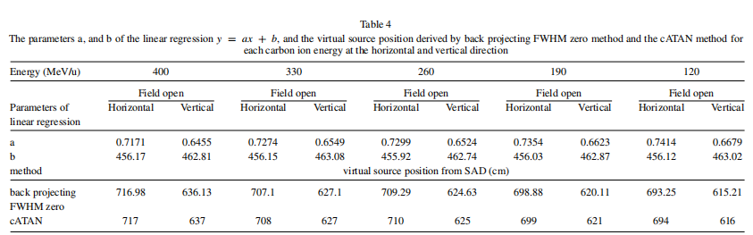
Table 4 shows the parameters a and b in the linear regression when y = 0, y denotes field size in y = ax + b, which means the virtual source position, x, happens at the back projection point when the field size becomes zero. The virtual source position derived by cATAN method was also listed in Table 4 for comparison with the results derived by back projecting HWFM to zero methods.
The solution of x, in y = ax + b, the parameters a, and b, were listed in Table 4 which were generated by the same process of back projecting HWFM to zero methods to get the virtual source position for every energy.
Mathematically, when the velocity of the particle v is perpendicular to the direction of the magnetic field, we can write, F = q(VXB), hence, the higher carbon ion energy in terms the higher velocity leads the stronger force to bend the carbon ion by the horizontal and vertical magnetism, therefore, the distance of virtual source positions is increased from SAD with high to low energy which was shown in Table 4.
The distance of the virtual source position of the carbon ion beam in the horizontal and vertical direction can be integrated as a function of carbon ion energy in Equations 1 and 2, respectively in Fig. 6. The virtual source position in the horizontal direction can be presented by VSh, where VSh = 0.0057,  VSh denotes the virtual source position in the horizontal direction, E means the virtual source position at this energy of the carbon ion beam.
The virtual source position in the vertical direction can be presented by VSv, where VSv = 0.0055,  , VSv denotes the virtual source position in the vertical direction, E means the virtual source position at this energy of the carbon ion beam. The relationship of virtual source position and carbon ion energy in horizontal and the vertical direction generated in equations 1 and 2, the comparison for calculation and measurements are agreed within 1%.
The MLC opening, as well as the fabrication of the compensator, were then corrected according to the measured virtual source position for every carbon ion energy in the horizontal and vertical directions. Furthermore, the MLC opening depends not only on the accuracy of the virtual source position but also depends on whether the MLC offset is carefully adjusted [18].
The film FWHM measurement error of 0.5 mm, which equals to the pixel size of 0.5 mm in a largeformat CMOS detector, leads to 0.001% deviation of α (cATAN) at every assumed textend. The overall uncertainty for the reproducibility of calculated virtual source position by the assumed textend in the vertical and horizontal directions amounts to 0.1%. The errors of calculated virtual source position by assumed textend with back projecting FWHM to zero methods were within 1.1 ± 0.001, p = 0.033.
5.Conclusion
The convergent arcTAN method for investigating virtual source position in carbon ion beam is different from the conventional back projecting HWFM method. The study regarding virtual source position in carbon ion is none, and we have developed an innovative technology capable of dealing with the virtual source position delivered by different carbon ion energies from scanning-passive scatter beam in our facility. The importance of the precise virtual source position in the Monta Carlo simulation is indispensable. The calculation of radiation doses may not always be in agreement for MLC treatment fields at a carbon ion beam treatment planning system unless the virtual source position and MLC offset are well-calibrated. The current method does not model effects from the MLC thickness nor of the compensator’s scattering. However, expansion of this method to incorporate these effects as well as in pencil scanning beam is possible and is currently being worked on.
Competing interests
There are no actual or potential competing interests in this study. This manuscript has not been published nor concurrently submitted for publication elsewhere.
Acknowledgments
The author appreciates Professor Qiang Li and Professor Yan-Cheng Ye for their great contribution to this study. Professor Yan-Cheng Ye is juxtaposed with the first author (co-first authors with equal contribution). Professor Qiang Li is juxtaposed with the correspondence author (co-corresponding authors with equal contribution).
This work is also supported by the Funding: Central government Guided Local fund projects of Science and Technology Department of Gansu Province, China. (The Precise therapy platform of clinical and research for radiation oncology in carbon ion therapy 22ZY1QH001).
This work was supported by project of Wuwei Science and Technology Bureau, (WW2002063).
References
[1] P. Shroder-Babo, Determination of the virtual electron source of a betatron, Acta Radiol 364(suppl) (1983), 7. 42.
[2] A. Jamshidi, F.T. Kuchnir and S.C. Reft, Determination of the source position for the electron beam from a high-energy linear accelerator, Med Phys 13 (1986), 942.
[3] F.M. Khan, W. Sewchand and S.H. Levitt, Effect of air space on depth dose in electron beam therapy, Radiology 126 (1978), 249.
[4] B. Gottschalk, A.M. Koehler and R.J. Schneider, Multiple Coulomb scattering of 160MeV protons, Nucl Instrum Methods Phys Res B 74 (1993), 467–490.
[5] T. Bortfeld and W. Schlegel, An analytical approximation of depth–dose distributions for therapeutic proton beams, Phys Med Biol 41 (1996), 1331–1339.
[6] P. Kimstrand, E. Traneus and A. Ahnesjo, A beam source model for scanned proton beams, Phys Med Biol 52 (2007), 3151–3168.
[7] H. Kooy, S. Rosenthal and M. Engelsman, The prediction of output factors for spread-out proton Bragg peak fields in clinical practice, Phys Med Biol 50 (2005), 5847–5856.
[8] H. Kooy, M. Schaefer and S. Rosenthal, Monitor unit calculations for range-modulated spread-out Bragg peak fields, Phys Med Biol 48 (2003), 2797–2808.
[9] P.L. Petti, Differential-pencil-beam dose calculation for charged particles, Med Phys 19 (1992), 137–149.
[10] P.L. Petti, Evaluation of a pencil-beam dose calculation technique for charged particle radiotherapy, Int J Radiat Oncol Biol Phys 35 (1996), 1049–1057.
[11] K.R. Russell, U. Isacsson and M. Saxner, Implementation of pencil kernel and depth penetration algorithms for treatment planning of proton beams, Phys Med Biol 45 (2000), 9–27.
[12] C. Abdullah, H. Farag, W. El-Sheshtawy, H. Aboelenein and O.W. Guirguis, Clinical impact of anisotropic analytical algorithm and Acuros XB dose calculation algorithm for intensity modulated radiation therapy in lung cancer patients, J Xray Sci Technol 29(6) (2021), 1019–1031.
[13] J.A. Meyer, J.R. Palta and K.R. Hogstrom, Determination of relatively new electron dosimetry measurement techniques on Mevatron 80, Med Phys 11 (1984), 670–677.
[14] R. Dreindl, D. Georg and M. Stock, Radiochromic film dosimetry: considerations on precision and accuracy for EBT2 and EBT3 type films, Med Phys 24(2) (2014), 153–163.
[15] T. Kamomae, Y. Miyabe and A. Sawada, Simulation for improvement of system sensitivity of radiochromic film dosimetry with different band-pass filters and scanner light intensities, Radiol Phys Technol 4(2) (2011), 140–147.
[16] O.A. García-Garduno, J.M. Larraga-Gutiérrez and M. Rodríguez-Villafuerte, Effect of correction methods of radiochromic EBT2 films on the accuracy of IMRT QA, App Radi Isot 107 (2016), 121–126.
[17] B. Schaffner, Proton dose calculation based on in-air fluence measurements, Phys Med Biol 53 (2008), 1545–1562.
[18] J. Wu, T. Lee and C. Kuo, A light field-based method to adjust rounded leaf end MLC position for split shape dose calculation correction in a radiation therapy treatment planning system, J Appl Clin Med Phys 13(6) (2012), 3–18.
Preliminary Review: Zhang Jie Final Review: Zhang Lihong